d,f,e/05.08/nr
|
|
|
- Jakob Sommer
- vor 6 Jahren
- Abrufe
Transkript


1 COMPONENTS MODULES ROBOTICS SYSTEMS Linear Technology Linearführungen Racks and pinions Zahnstangen und Ritzel Bevel gears Kegelräder Worm gear units: 07 High Performance Servo Worm Gear Units Schneckengetriebe: 07 Hochleistungs-Servoschneckengetriebe d,f,e/05.08/nr i
2 Die Angaben in diesem Katalog wurden mit äusserster Sorgfalt erarbeitet und geprüft. Trotzdem kann für fehlerhafte oder unvollständige Angaben keine Haftung übernommen werden. Nachdruck, auch auszugsweise, ist nur mit unserer Genehmigung gestattet. Änderungen im Sinne technischer Verbesserungen bleiben vorbehalten. Ce catalogue a été soigneusement composé et toutes ses données vérifiées. Toutefois, nous déclinons toute responsabilité en cas d erreurs ou d omissions. Par suite du développement constant de nos recherches, nous devons nous réserver tout droit de modifications de produits de notre fabrication. This catalogue has been produced with a great deal of care and attention. All data has been checked for accuracy. However, no liability can be accepted for any incorrect or incomplete data. All rights reserved. Reproduction in whole or in part without our authorisation is prohibited.
3 GÜDEL AG Industrie Nord CH-4900 Langenthal Switzerland phone fax GÜDEL GmbH Carl-Benz-Strasse 5 D Altenstadt Germany phone fax info@de.gudel.com GÜDEL Inc Runway Blvd. US-Ann Arbor, MI USA phone fax info@us.gudel.com ALL LOCAL REPRESENTATIONS SEE:
4 Einführung Introduction Introduction Der vorliegende Katalog umfasst die Komponenten der Linear- und Antriebstechnik. Der Inhalt widerspiegelt die Erfahrung von mehr als 5 Jahrzehnten der Entwicklung und Fertigung von Längsführungen,Verzahnungen und Getriebebau. Das nach ISO 9001: 2000 aufgebaute Qualitätssystem, eine grosse Lagerhaltung und ein weltweites Vertriebsnetz garantieren einen optimalen Kundennutzen. Das umfangreiche Standardprogramm ermöglicht einen schnellen Zugriff auf alle Komponenten. Ein erfahrenes Ingenieurteam hilft Ihnen bei der Auswahl, erarbeitet mit Ihnen Einbauvorschläge und optimiert Ihren Anwendungsfall. Auch Sonderteile nach Ihren Zeichnungen stellen wir gerne für Sie her. Sprechen Sie mit uns! Le catalogue suivant comprend les composants de la technique linéaire et d'entraînement. Le contenu reflète l'expérience de plus de 5 décennies de développement et de fabrication de guides longitudinaux, de dentures et de construction d'engrenages. Le système de qualité élaboré selon ISO 9001: 2000, un stock important et un réseau de distribution mondial garantissent au client un profit optimal. La riche gamme standard permet un accès rapide à tous les composants. Une équipe d'ingénieurs expérimentés vous aidera à choisir, travaillera avec vous des projets de montage et optimisera votre cas d'application. Nous fabriquerons également des pièces spéciales pour vous selon vos dessins. Parlez-nous de vos applications! This catalogue covers all the components of the linear and drive technology. Its content reflects the experience of more than 5 decades in the development and manufacture of linear guides, gears and gearboxes. A quality system based on ISO 9001: 2000, a large inventory and a global distribution network guarantee optimal benefits to the customer. The extensive standard programme makes rapid access to all components possible at all times. An experienced engineering team will help you in your selection, and assist you in drawing up installation proposals and in the optimisation of your application. We will also be pleased to manufacture custom components to your own drawings. Call us! Qualitätskontrolle Production et qualité Quality control Um die hohen Qualitätsanforderungen unserer Kundschaft zu erfüllen, werden die Module auf modernsten Werkzeugmaschinen in eigenen Werken gefertigt. Die Qualitätskontrolle geschieht gemäss ISO 9001 als Erststück- und Stichprobenkontrolle. Dies garantiert unserer Kundschaft den Erwerb eines qualitativ hochwertigen Produktes. Pour satisfaire les exigences de notre clientèle, les modules sont fabriqués dans nos propres usines par des machines modernes. Le contrôle de qualité est fait suivant les exigences de la norme ISO Tous ces efforts garantissent à notre clientèle un produit de haute qualité. To meet the high requirements of our clients, the modules are manufactured in our factories by modern machine tools. Quality control is carried out in accordance with ISO This guarantees our clients a continuous high product quality. 00.D

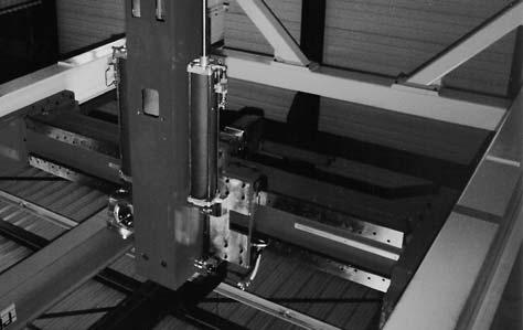
5 Hochleistungs-Servogetriebe Servoréducteur à haute performance High performance servo Gear Units Die AE-Baureihe kompakter Hochleistungs- Servoschneckengetriebe wird in 6 Baugrössen und Übersetzungen von 2:1 bis 24:1 hergestellt. Sie ist geeignet wo ein Höchstmass an Dynamik und Zuverlässigkeit gefordert wird. Die Exzenterflansche der Abtriebslagerung erlauben ein einfaches Ein- und Nachstellen des Verzahnungsspiels. Die Spezialkupplung an der Eintriebsseite und die Schrumpfscheibe an der Abtriebsseite gewährleisten einen spielfreien Kraftfluss. Unsere Ingenieure, denen entsprechende Rechnungsprogramme zur Verfügung stehen, helfen Ihnen gerne Ihren Anwendungsfall zu optimieren. La gamme des Servoréducteurs compacts de type AE est fabriquée en 6 tailles avec des rapports de réduction allant de 2:1 à 24:1. Ils sont recommandes où un grand rendement et une grande fiabilité sont nécessaires. Les brides excentriques des paliers de sortie permettent de régler et de rattraper de manière simple le jeu entre la vis et la roue. L accouplement au niveau de l entrée moteur ainsi que la jonction de serrage au niveau de l arbre de sortie permettent de garantir une transmission de puissance exempt de jeu. De plus nos ingénieurs, à l aide de programmes de calcule sont à votre disposition afin d optimiser vos applications. The AE-range of compact servo worm gear units are manufactured in 6 model sizes, with reductions from 2:1 to 24:1.They are suitable for use when a high efficiency and reliability are required. The eccentric flanges of the hollow output shaft permit a simple setting and readjusting of the worm and wheel backlash.the drive coupling on the input shaft and a tension set on the hollow output shaft guarantee a power transmission torsion free and without backlash. Our engineers are equipped with calculation programs and will be glad to help you to find the right product for your application. Bild 1 Bild 1 Testing of gear boxes 07.00

6 INHALTSVERZEICHNIS TABLE DES MATIÈRES / CONTENT PRODUKTÜBERSICHT Gamme de produits Product overview BAUKASTEN Le système modulaire The modular system AUSWAHLTABELLE Sélection du Réducteur standard Selection of standard worm gear unit BAUGRÖSSEN 030 Tailles de fabrication 030 Sizes BAUGRÖSSEN: 045 Taille de fabrication: 045 Size: BAUGRÖSSEN: 060 Taille de fabrication: 060 Size: BAUGRÖSSEN: 090 Taille de fabrication: 090 Size: BAUGRÖSSEN: 120 Taille de fabrication: 120 Size: BAUGRÖSSEN: 180 Taille de fabrication: 180 Size: BERECHNUNGSBEISPIEL Exemple de calcul Calculation example WARTUNG Entretien Maintenance EINBAU- UND AUSBAU Montage Assembly MOTOREN APPLIKATIONEN Applications des moteurs Applications of motors ANWENDUNGEN Exemple d application Sample application


7 PRODUKTÜBERSICHT GAMME DES PRODUITS PRODUCT OVERVIEW Hochleistungs-Schneckengtriebe Réducteurs à haute performance Worm gear unit
8 BAUKASTEN LE SYSTÈME MODULAIRE THE MODULAR SYSTEM Die AE-Baureihe kompakter Hochleistungs- Servoschneckengetriebe werden in 5 Baugrössen und 10 Untersetzungen hergestellt. Die Baugrösse ist identisch mit dem Achsabstand. La gamme des servoréducteurs compacts de type AE est fabriquée suivant 5 tailles avec des rapports de réduction allant de 2:1 a 24:1. La taille correspond à l'entraxe du servoréducteur. The AE-range of compact high performance gearboxes is available in 5 model sizes and 10 standard ratios. The gearbox size is identical to the centreline distance. Baugrössen Taille Size Übersetzung Ratio 2:1 3:1 4:1 5:1 6:1 8:1 10: /3:1 16:1 24:1 Zahnspiel Jeu axial Backlash 3 6 Arc Min Das grosse Untersetzungsprogramm erlaubt eine optimale Abstimmung der Hochleistungs- Schneckengetriebe mit dem Servoantriebspaket. Die Zahnungen der Getriebe sind nach DIN 3975/76 ausgelegt und so optimiert, dass eine Spieleinstellung der Verzahnung über die Abtriebs-Exzenterflansche erfolgen kann. Die Gehäuse sind allseitig bearbeitet und haben Befestigungs- sowie Gewindebohrungen. Kühlrippen garantieren einen optimalen Abfluss der Wärme. Die synthetische Schmierung gewährleistet lange Lebensdauer sowie hohen Wirkungsgrad und grosse Laufruhe. Eine Spezialkupplung an der Eintriebsseite und eine Schrumpfscheibenkupplung an der Abtriebsseite garantieren einen spielfreien Kraftfluss und den Anbau eines beliebigen Motors. Die Auswahl- und Belastungstabellen sind auf Seite für Getriebe und Seite für Zahnstangen und Ritzel. Für Auslegungs- und Berechnungsbeispiele verweisen wir auf Seiten La grande variété de rapports de réductions permet d'obtenir un choix optimum avec un système asservis. Les couples roues et vis et la denture sont réalisés selon la norme DIN 3975/76 et le rattrapage du jeu se fait avec les brides excentriques des paliers de sortie. Le carter est usiné sur tous les côtés et les trous de fixation permettent différentes positions de montage. La conception des aillettes permet d obtenir une excellente dissipation thermique. La lubrification avec une huile synthétique garantit un grand rendement et un fonctionnement silencieux. L'accouplement de l'entrée moteur ainsi que la jonction de serrage ou niveau de l'arbre de sortie permettent une transmission de puissance exempt de jeu et le montage de tous types de moteurs. Les tableaux de charge des réducteurs sont à la page et pour les crémaillères, pignons page Un exemple de calcul est présenté en page The large range of gearbox ratio's allows to match the exact requirement of the Servo Drive system. Worm and wormwheel are manufactured to DIN 3975/76 and the geometrical dimensions of the tooth is optimized so the backlash can be adjusted by using the eccentric hub of the output flanges. The casings are fully machined and with its many fixing bores and tapped holes allowing mounting in any positions. The integrated fins of the housing dissipate the heat and maintain an optimum running temperature. The synthetic special oil for lubrication ensures a high degree of efficiency and smooth operation. A special clutch on the input and a discplate coupling on the output shaft guarantee largely torsion and backlash free connections and mounting of any type of motors. The selections- and load tables are on page for gear boxes and on page for racks and pinions. Calculation example is on page
9 WAHL DES SERVO SCHNECKENGETRIEBES SÉLECTION DU RÉDUCTEUR À HAUTE PERFORMANCE SELECTION OF WORM GEAR DRICE UNIT Die Getriebe sind für den Einsatz mit Dreh- und Gleichstrom-Servomotoren ausgelegt. Die Exzenterflansche der Abtriebslagerung erlauben ein einfaches Ein- und Nachstellen des Verzahnungsspiels. Die Einheiten werden im Werk mit einem Verzahnspiel von < 6 eingestellt. Les réducteurs ont été developpés pour être utilisés avec des moteurs d'asservissement. La bride excentrique du palier de sortie premet de régler et de rattraper de manière facile le jeu axial de la denture. Sortie d'usine les réducteurs sont réglés avec un jeu de < 6. These high performance worm gearboxes were especially developed for use in high performance Servo-Driven Systems.The backlash is adjustable and is set by rotating the two eccentric flanges located on either side of the gearbox housing. The units are set up in the factory with a backlash < 6. Richtlinien für die Getriebewahl Die in der Tabelle aufgeführten Abtriebsmomente T2N (Nm) sind gültig für den Einsatz im stossfreien Servo-Betrieb bei 20 C Umgebungstemperatur. Bei höheren Belastungen sind die Tabellenwerte mit den nachstehenden Faktoren zu korrigieren. Sélectionner un réducteur Les couples indiquées dans le tableau,t2n (Nm) sont valables pour des systèmes d'asservissement, fonctionnant sans chocs et à 20 C de température ambiante. Pour d'autres conditions les valeurs sont à corriger avec les coefficients selon tableaux. Selecting a unit The nominal torque T2N (Nm) is valid for servo applications that run under normal shock free operations and at an ambient temperature of 20 C. Other conditions have to be corrected by factors shown below. Zusätzlich zu den erwähnten Betriebsfaktoren ist ein Sicherheitsfaktor einzurechnen, der Ihren Erfahrungen und den anwendungsspezifischen Sicherheitsanforderungen entspricht. Baugrössen 120 und 180: Bei Eintriebs-Drehzahlen über 1500 min -1 und gleichzeitiger Einschaltdauer über 80%, bitten wir Sie mit Güdel Kontakt aufzunehmen. Pour toutes applications paticulières il est nécessaire de mettre un coefficient de sécurité supplémentaire aux coefficients déjà défini dans le tableau, celui-ci correspondant à chacune des applications client. Tailles 120 et 180: En cas de vitesse de rotation à l entrée supérieure à 1500 min -1 et un cycle de fonctionnement supérieur à 80% veuillez contacter Güdel s.v.p. For specific applications it may be necessary to consider a safety factor, in addition to the factors alredy mentioned in the catalogue. This factor must be based on the customer s experience and any regulations specific to the application. Sizes 120 and 180: In the case of an input speed higher than 1500 min -1 with a duty cycle higher than 80%, please contact Güdel. T2N Mech. T2 fb fa T2N Therm. T2 ft fed Beide Gleichungen müssen erfüllt sein / both required / Betriebsfaktor / Coefficient de marche / Service coefficient Antrieb Polynomia Standard Servo / FU/VFD AC-Motor External Sinus 2 Output-shock fb Anlauffaktor / Coefficient de démarrage / Starting factor Anlaufhäufigkeit / Fréquence de démarrage / Starting frequency 60/h 360/h 1200/h 3600/h fa Temperaturfaktor / Coefficient de température / Temperature factor Umgebungstemperatur / Température ambiante / Ambient temperature 10 C 20 C 30 C 40 C 50 C ft Einschaltdauerfaktor / Coefficient de service / Duty factor Einschaltdauer / Cycle de service / Duty cycle 25% 40% 60% 70% 100% fed T2 (Nm): Drehmoment der Maschine / Couple de la machine / Required torque for driven machine Zulässige Belastungen auf die Abtriebswelle Treten neben hohen Radialkräften gleichzeitig Axialkräfte auf, erbitten wir um Rückfrage. Die Abtriebsglocken mit der Ritzellagerung müssen konstruktiv abgestützt werden. Siehe Fig. ➀. Charges admissibles au niveau de l arbre de sortie Si les charges radiales et axiales sont très importantes nous vous prions de nous consulter. Il est nécessaire de considérer dans la construction un support pour le palier du pignon de la bride de sortie voir Fig. ➀. Permissible output shaft loads In case of very high radial and axial loads please contact us. The output flange with the pinion bearing must be supported see Fig. ➀. Typ AE 030 AE 045 AE 060 AE 090 AE 120 AE 180 L1 (mm) F1Max (N) L2 (mm) F2Max (N) Fig. ➀
10 Leistungstabellen Tableau des caractéristiques Efficiency tables n1 (min -1 ) Typ i T2max P1 T2N η P1 T2N η P1 T2N η P1 T2N η P1 T2N η P1 T2N η AE ,97 4,9 0,79 1,72 5,9 0,81 1,39 7,4 0,84 0,91 10,0 0,86 0,68 11,3 0,86 0,40 12,9 0,85 3 2,05 7,8 0,79 1,76 9,2 0,82 1,40 11,2 0,84 0,88 14,4 0,86 0,65 16,0 0,86 0,37 17,9 0,84 4 1,89 9,4 0,78 1,61 11,0 0,81 1,25 13,3 0,83 0,77 16,7 0,85 0,56 18,3 0,85 0,32 20,1 0,83 5 1,54 9,4 0,77 1,33 11,0 0,78 1,02 13,1 0,81 0,62 16,2 0,83 0,44 17,5 0,83 0,25 19,2 0,81 6 1,20 8,6 0,75 1,02 9,9 0,76 0,79 11,7 0,77 0,47 14,3 0,80 0,34 15,5 0,81 0,18 16,9 0,80 8 1,10 10,1 0,72 0,94 11,6 0,73 0,72 13,7 0,74 0,42 16,6 0,77 0,30 17,9 0,77 0,17 19,4 0, ,88 9,5 0,68 0,74 10,9 0,69 0,57 12,8 0,71 0,33 15,4 0,73 0,24 16,6 0,74 0,13 17,9 0, /3 0,72 9,4 0,62 0,59 10,8 0,65 0,44 12,6 0,67 0,26 15,1 0,68 0,19 16,2 0,68 0,10 17,5 0, ,74 10,5 0,56 0,59 12,0 0,60 0,44 14,0 0,62 0,26 16,9 0,64 0,18 18,1 0,65 0,10 19,5 0, ,57 10,3 0,47 0,45 11,8 0,51 0,34 13,7 0,53 0,20 16,4 0,54 0,14 17,6 0,55 0,08 19,0 0,54 AE ,95 16,2 0,85 5,41 20,0 0,87 4,63 26,0 0,88 3,29 37,4 0,89 2,57 43,8 0,89 1,57 52,7 0,88 3 6,34 26,0 0,86 5,69 31,6 0,87 4,76 40,3 0,89 3,25 55,4 0,89 2,48 63,3 0,89 1,47 73,9 0,88 4 5,90 32,0 0,85 5,23 38,5 0,87 4,32 48,3 0,88 2,87 64,8 0,89 2,17 73,1 0,88 1,27 83,9 0,87 5 4,88 32,4 0,84 4,28 38,7 0,85 3,48 48,1 0,87 2,27 63,4 0,88 1,70 71,0 0,87 0,98 80,5 0,86 6 3,83 29,6 0,81 3,33 35,2 0,83 2,67 43,4 0,85 1,71 56,5 0,86 1,27 62,9 0,86 0,73 70,8 0,85 8 3,53 35,2 0,79 3,04 41,6 0,81 2,42 51,0 0,83 1,55 65,8 0,84 1,14 72,9 0,84 0,65 81,7 0, ,79 33,2 0,75 2,39 39,2 0,77 1,89 47,8 0,80 1,18 61,3 0,81 0,87 67,7 0,81 0,50 75,5 0, /3 2,22 33,0 0,70 1,88 38,8 0,73 1,48 47,2 0,75 0,92 60,3 0,77 0,68 66,4 0,77 0,39 73,9 0, ,19 36,8 0,66 1,82 43,3 0,70 1,44 52,7 0,72 0,89 67,2 0,74 0,66 74,0 0,73 0,35 75,0 0, ,63 36,1 0,58 1,35 42,5 0,62 1,06 51,6 0,64 0,65 65,6 0,66 0,48 72,2 0,65 0,27 77,9 0,63 AE , ,88 11, ,89 10, ,90 7, ,90 6, ,90 3, , , ,88 12, ,89 10, ,90 7, ,91 6, ,90 3, , , ,88 11, ,89 9, ,90 6, ,90 5, ,90 3, , , ,87 9, ,88 8, ,89 5, ,89 4, ,89 2, ,88 6 8, ,85 7, ,87 6, ,88 4, ,89 3, ,88 1, ,87 8 7, ,83 6, ,84 5, ,86 3, ,86 2, ,86 1, , , ,80 5, ,82 4, ,83 2, ,84 2, ,84 1, , /3 4, ,75 4, ,78 3, ,80 2, ,81 1, ,81 0, , , ,72 3, ,75 3, ,77 2, ,78 1, ,77 0, , , ,64 2, ,67 2, ,69 1, ,70 1, ,70 0, ,67 AE , ,91 29, ,92 23, ,92 19, ,92 13, , , ,92 31, ,92 24, ,93 19, ,92 12, , , ,92 29, ,92 22, ,92 17, ,92 11, , , ,91 23, ,92 17, ,92 14, ,92 8, , , ,90 18, ,91 13, ,91 10, ,91 6, , , ,88 16, ,89 12, ,90 9, ,89 5, , , ,86 12, ,88 9, ,88 7, ,88 4, , /3 11, ,83 9, ,85 7, ,85 5, ,85 3, , , ,81 9, ,82 6, ,83 5, ,82 2, , , ,74 6, ,76 4, ,77 3, ,76 2, ,74 AE , ,93 65, ,93 54, ,94 46, ,94 33, , , ,93 70, ,94 56, ,94 47, ,94 32, , , ,93 65, ,93 51, ,94 42, ,94 28, , , ,93 53, ,93 41, ,93 34, ,93 22, , , ,92 41, ,93 31, ,93 25, ,93 16, , , ,91 37, ,91 28, ,91 23, ,91 14, , , ,89 28, ,90 21, ,90 17, ,90 11, , /3 25, ,87 22, ,88 16, ,88 13, ,88 8, , , ,84 21, ,85 15, ,86 12, ,85 7, , , ,79 14, ,80 11, ,80 8, ,80 5, ,78 AE / i:ab Lager / du stock / ex stock n 1 (min -1 ) : Eintriebsdrehzahl / Vitesse d entrée / input speed T 2Max (Nm) : Max. Drehmoment bei Not Aus / Couple max. en cas d arrêt d urgence / Max. torque in case of emergency stop. T 2N (Nm) : Nenndrehmoment am Abtrieb / Couple de sortie nominale / Nominal output torque P 1 (kw) : Eintriebsleistung / Puissance d entrée / Input power η : Wirkungsgrad / Rendement / Efficiency 07.05
11 BAUGRÖSSE 030 TAILLE 030 SIZE 030 Hochleistungs-Schneckengetriebe Réducteur à haute performance Worm gear unit a = 30 mm 20 < L < 33 L ausgelegt für Flansch mit t 1 = 12mm L sur la base d une épaisseur de flange t 1 = 12mm L based on a flange thickness t 1 = 12mm Pos. ➄ Pos. ➃ Pos. ➀ Pos. ➅ AE 030/L DIN Fig. ➁ Fig. ➀ AE 030/R Pos. ➀ Getriebe / Réducteur / Worm gear unit Type Part No. Ratio Inertia L i J red (10-7 kg m 2 ) m (kg) AE 030/L : AE 030/R : 1 69 AE 030/S : : : : : : : : 1 15 i: ab Lager / sur stock / from stock AE 030/S Pos. ➃ Flansch / Bride / Flange Part No. Fig. S r F t1 t2 D M m (kg) ➀ M ➀ M ➀ M ➀ M ➀ M ➀ M ➀ M ➀ M ➀ M ➁ , ➁
12 Pos. ➄ Kupplung / Accouplement / Coupling Fig. ➀ Inertia Part No. Fig. d J (10-6 kg m 2 ) T1max (Nm) MA (Nm) m (kg) ➀ M3x ➀ M3x ➀ M3x ➀ M3x ➀ M3x16 T1max: maximal übertragbares Moment der Kupplung / Couple max. de l accouplement / Maximum torque of coupling MA: Anziehdrehmoment / Couple de serrage / Tightening torque Pos. ➅ Schrumpfscheiben-Kupplung / Jonction arbre-moyeu / Tension set Inertia Part No. J (10-6 kg m 2 ) T2max (Nm) m (kg) M A 5 Nm T2max: maximal übertragbares Moment der Kupplung / Couple max. de l accouplement / Maximum torque of coupling J red = J / i 2 Zubehör Accessoires Accessories Pos. ➁ Abtrieb mit Ritzel / Bride de sortie avec pignon / Output flange with pinion Part No. Module p z D 0 D k D 1 L 4 L 5 L 6 J m (kg) p (mm):teilung / pas / pitch J (10-6 kg m 2 ): Inertia J red = J / i 2 Pos. ➂ Distanzstücke / Entretoise / Spacer Part No. Mat. L 7 m (kg) Alu Bestellbeispiel Exemple de commande Ordering example Pos. ➀ AE 030/L: i: 8:1 Zubehör Pos. ➃ Pos. ➁ Pos. ➄ Pos. ➂ Pos. ➅ Angaben für speziellen Flansch und Kupplung Spécification pour la bride de sortie et l accouplement spéciale Specification for special flange and coupling d : [mm] L : [mm] S : [mm] r : [mm] F : [mm] ØM : M : alternativ M t : [mm] [mm] [mm] Motor D : alternativ [mm] 07.07
13 BAUGRÖSSE 045 TAILLE 045 SIZE 045 Hochleistungs-Schneckengetriebe Réducteur à haute performance Worm gear unit a = 45 mm 33 L2 < < L1 < 33 L ausgelegt für Flansch mit t 1 = 14mm L sur la base d une épaisseur de flange t 1 = 14mm L based on a flange thickness t 1 = 14mm Pos. ➄ Pos. ➃ Pos. ➀ Pos. ➅ AE 045/L DIN Fig. ➁ Fig. ➀ Pos. ➀ Getriebe / Réducteur / Worm gear unit Type Part No. Ratio Inertia L 1 L 2 i J red (10-6 kg m 2 ) m (kg) AE 045/L : ,5 AE 045/R : 1 47 AE 045/S : : : : : : : : 1 6 i: ab Lager / sur stock / from stock AE 045/R AE 045/S Pos. ➃ Flansch / Bride / Flange Part No. Fig. S r F t1 t2 D M m (kg) ➀ M ➀ M ➀ M ➀ M ➀ M ➀ M ➀ M ➀ M ➀ M ➀ M ➀ M ➁ ø ➁ ø


 404 550 1.5915 5.0 20 31.")
 404 560 ➀ Alu 19 0.")
14 Pos. ➄ Kupplung / Accouplement / Coupling Fig. ➀ Inertia Part No. Fig. d J (10-6 kg m 2 ) T1max (Nm) MA (Nm) m (kg) ➀ M4x ➀ M4x ➀ M4x ➀ M4x ➀ M4x16 T1max: maximal übertragbares Moment der Kupplung / Couple max. de l accouplement / Maximum torque of coupling MA: Anziehdrehmoment / Couple de serrage / Tightening torque Pos. ➅ Schrumpfscheiben-Kupplung / Jonction arbre-moyeu / Tension set Inertia Part No. J (10-6 kg m ) 2 T2max (Nm) m (kg) M A 6.5 Nm T2max: maximal übertragbares Moment der Kupplung / Couple max. de l accouplement / Maximum torque of coupling J red = J / i 2 Zubehör Accessoires Accessories Pos. ➁ Abtrieb mit Ritzel / Bride de sortie avec pignon / Output flange with pinion Part No. Module p z D 0 D k D 1 L 4 L 5 L 6 J m (kg) p (mm):teilung / pas / pitch J (10 kg m ): Inertia -6 2 J red = J / i 2 Pos. ➂ Distanzstücke / Entretoise / Spacer Part No. Mat. L 7 m (kg) ➀ Alu ➀ Lieferung paarweise / Livraison par paire / Delivery in pairs only Bestellbeispiel Exemple de commande Ordering example Pos. ➀ AE 045/L: i: 5:1 Zubehör Pos. ➃ Pos. ➁ Pos. ➄ Pos. ➂ Pos. ➅ Angaben für speziellen Flansch und Kupplung Spécification pour la bride de sortie et l accouplement spéciale Specification for special flange and coupling d : [mm] L : [mm] S : [mm] r : [mm] F : [mm] ØM : M : alternativ M t : [mm] [mm] [mm] Motor D : alternativ [mm] 07.09
15 BAUGRÖSSE 060 TAILLE 060 SIZE 060 Hochleistungs-Schneckengetriebe Réducteur à haute performance Worm gear unit a = 60 mm 50 L 3 < L 2 < < L 1 < 40 L ausgelegt für Flansch mit t 1 = 14mm L sur la base d une épaisseur de flange t 1 = 14mm L based on a flange thickness t 1 = 14mm Pos. ➄ Pos. ➃ Pos. ➀ Pos. ➅ AE 060/L DIN Fig. ➁ Fig. ➀ AE 060/R Pos. ➀ Getriebe / Réducteur / Worm gear unit Type Part No. Ratio Inertia L 1 L 2 L 3 i J red (10-6 kg m 2 ) m (kg) AE 060/L : AE 060/R : AE 060/S : : : : : : : 1 30 i: ab Lager / sur stock / from stock 24 : 1 27 Pos. ➃ Flansch / Bride / Flange AE 060/S Part No. Fig. S r F t1 t2 D M m (kg) ➀ M ➀ M ➀ M ➀ M ➀ M ➀ M ➀ M ➀ M ➀ M ➀ M ➀ M ➁ ø ➁ M10
16 Pos. ➄ Kupplung / Accouplement / Coupling Fig. ➀ Fig. ➁ Inertia Part No. Fig. d J (10-6 kg m 2 ) T1max (Nm) MA (Nm) m (kg) ➀ M6x ➀ M6x ➀ M6x ➁ M4x ➁ M4x16 T1max: maximal übertragbares Moment der Kupplung / Couple max. de l accouplement / Maximum torque of coupling MA: Anziehdrehmoment / Couple de serrage / Tightening torque Fig. ➁ nur mit L3 einsetzbar / Fig. ➁ impose longueur L3 / Fig. ➁ requires lenght L3. Pos. ➅ Schrumpfscheiben-Kupplung / Jonction arbre-moyeu / Tension set Inertia Part No. J (10-6 kg m 2 ) T2max (Nm) m (kg) M A 6.5 Nm T2max: maximal übertragbares Moment der Kupplung / Couple max. de l accouplement / Maximum torque of coupling J red = J / i 2 Zubehör Accessoires Accessories Pos. ➁ Abtrieb mit Ritzel / Bride de sortie avec pignon / Output flange with pinion Part No. Module p z D 0 D k D 1 L 4 L 5 L 6 J m (kg) p (mm):teilung / pas / pitch J (10-6 kg m 2 ): Inertia J red = J / i 2 Pos. ➂ Distanzstücke / Entretoise / Spacer Part No. Mat. L 7 m (kg) ➀ Alu ➀ Alu ➀ Lieferung paarweise / Livraison par paire / Delivery in pairs only Bestellbeispiel Exemple de commande Ordering example Pos. ➀ AE 060/L: i: 5:1 Zubehör Pos. ➃ Pos. ➁ Pos. ➄ Pos. ➂ Pos. ➅ Angaben für speziellen Flansch und Kupplung Spécification pour la bride de sortie et l accouplement spéciale Specification for special flange and coupling d : [mm] L : [mm] S : [mm] r : [mm] F : [mm] ØM : M : alternativ M t : [mm] [mm] [mm] Motor D : alternativ [mm] 07.11
17 BAUGRÖSSE 090 TAILLE 090 SIZE 090 Hochleistungs-Schneckengetriebe Réducteur à haute performance Worm gear unit a = 90 mm 62 L2 < < L1 < 62 L ausgelegt für Flansch mit t 1 = 18mm L sur la base d une épaisseur de flange t 1 = 18mm L based on a flange thickness t 1 = 18mm DIN Pos. ➄ Pos. ➃ Pos. ➀ Pos. ➅ AE 090/L Fig. ➁ Fig. ➀ Pos. ➀ Getriebe / Réducteur / Worm gear unit Type Part No. Ratio Inertia L1 L2 i J red (10-5 kg m 2 ) m (kg) AE 090/L : AE 090/R : AE 090/S : : : : : : : 1 23 i: ab Lager / sur stock / from stock 24 : 1 21 AE 090/R AE 090/S Pos. ➃ Flansch / Bride / Flange Part No. Fig. S r F t1 t2 D M m (kg) ➀ M ➀ M ➀ M ➀ M ➀ M ➀ M ➀ M ➀ M ➀ M ➀ M ➀ M ➀ M ➁ ø ➁ ø ➁ ø
18 Pos. ➄ Kupplung / Accouplement / Coupling Fig. ➀ Fig. ➁ Inertia Part No. Fig. d J (10-6 kg m 2 ) T1max (Nm) MA (Nm) m (kg) ➀ M8x ➀ M8x ➀ M8x ➀ M8x ➀ M8x ➁ M6x ➁ M6x20 T1max: maximal übertragbares Moment der Kupplung / Couple max. de l accouplement / Maximum torque of coupling / MA: Anziehdrehmoment / Couple de serrage / Tightening torque Fig. ➁ nur mit L2 einsetzbar / Fig. ➁ impose longueur L2 / Fig. ➁ requires lenght L2. Pos. ➅ Schrumpfscheiben-Kupplung / Jonction arbre-moyeu / Tension set Inertia Part No. J (10-6 kg m 2 ) T2max (Nm) m (kg) T2max: maximal übertragbares Moment der Kupplung / Couple max. de M A l accouplement / Maximum torque of coupling 12 Nm J red = J / i 2 Zubehör Accessoires Accessories Pos. ➁ Abtrieb mit Ritzel / Bride de sortie avec pignon / Output flange with pinion Part No. Module p z D 0 D k D 1 L 4 L 5 L 6 J m (kg) p (mm):teilung / pas / pitch J (10-6 kg m 2 ): Inertia J red = J / i 2 Pos. ➂ Distanzstücke / Entretoise / Spacer Part No. Mat. L 7 m (kg) ➀ Alu ➀ Alu ➀ Lieferung paarweise / Livraison par paire / Delivery in pairs only Bestellbeispiel Exemple de commande Ordering example Pos. ➀ AE 090/S: i: 16:1 Zubehör Pos. ➃ Pos. ➁ Pos. ➄ Pos. ➂ Pos. ➅ Angaben für speziellen Flansch und Kupplung Spécification pour la bride de sortie et l accouplement spéciale Specification for special flange and coupling d : [mm] L : [mm] S : [mm] r : [mm] F : [mm] ØM : M : alternativ M t : [mm] [mm] [mm] Motor D : alternativ [mm] 07.13
19 BAUGRÖSSE 120 TAILLE 120 SIZE 120 Hochleistungs-Schneckengetriebe Réducteur à haute performance Worm gear unit a = 120 mm 79 L3 < L2 < < L1 < 59 L ausgelegt für Flansch mit t 1 = 20mm L sur la base d une épaisseur de flange t 1 = 20mm L based on a flange thickness t 1 = 20mm DIN Pos. ➄ Pos. ➃ Pos. ➀ Pos. ➅ AE 120/L Fig. ➁ Fig. ➀ Pos. ➀ Getriebe / Réducteur / Worm gear unit Type Part No. Ratio Inertia L1 L2 L3 i J red (10-5 kg m 2 ) m (kg) AE 120/L : AE 120/R : AE 120/S : : : : : / 3 : : 1 93 i: ab Lager / sur stock / from stock 24 : 1 82 Pos. ➃ Flansch / Bride / Flange AE 120/R AE 120/S Part No. Fig. S r F t1 t2 D M m (kg) ➀ M10 1, ➀ MI ➀ MI ➀ M ➀ M ➀ M ➀ M ➀ M ➁ ø ➁ ø ➁ ø
20 Pos. ➄ Kupplung / Accouplement / Coupling Fig. ➀ Fig. ➁ Pos. ➅ Schrumpfscheiben-Kupplung / Jonction arbre-moyeu / Tension set M A 12 Nm Pos. ➁ Abtrieb mit Ritzel / Bride de sortie avec pignon / Output flange with pinion Inertia Part No. Fig. d J (10-6 kg m 2 ) T1max (Nm) MA (Nm) m (kg) ➀ M8x ➀ M8x ➀ M8x ➀ M8x ➀ M8x ➁ M6x T1max: maximal übertragbares Moment der Kupplung / Couple max. de l accouplement / Maximum torque of coupling / MA: Anziehdrehmoment / Couple de serrage / Tightening torque Fig. ➁ nur mit L2, L3 einsetzbar / Fig. ➁ impose longueur L2, L3 / Fig. ➁ requires lenght L2, L3. Inertia Part No. J (10-6 kg m 2 ) T2max (Nm) m (kg) T2max: maximal übertragbares Moment der Kupplung / Couple max. de l accouplement / Maximum torque of coupling J red = J / i 2 Zubehör Accessoires Accessories Part No. Module p z D 0 D k D 1 L 4 L 5 L 6 J m (kg) p (mm):teilung / pas / pitch J (10-6 kg m 2 ): Inertia J red = J / i 2 Pos. ➂ Distanzstücke / Entretoise / Spacer Part No. Mat. L 7 m (kg) ➀ Alu ➀ Alu ➀ Lieferung paarweise / Livraison par paire / Delivery in pairs only Bestellbeispiel Exemple de commande Ordering example Pos. ➀ AE 120/L: i: 5:1 Zubehör Pos. ➃ Pos. ➁ Pos. ➄ Pos. ➂ Pos. ➅ Angaben für speziellen Flansch und Kupplung Spécification pour la bride de sortie et l accouplement spéciale Specification for special flange and coupling d : [mm] L : [mm] S : [mm] r : [mm] F : [mm] ØM : M : alternativ M t : [mm] [mm] [mm] Motor D : alternativ [mm] 07.15
21 BAUGRÖSSE 180 TAILLE 180 SIZE 180 Hochleistungs-Schneckengetriebe Réducteur à haute performance Worm gear unit a = 180 mm L ausgelegt für Flansch mit t 1 = 26mm L sur la base d une épaisseur de flange t 1 = 26mm L based on a flange thickness t 1 = 26mm 90 L2 < < L1 < 90 Pos. ➄ Pos. ➃ Pos. ➀ Pos. ➅ AE 180/L AE 180/R Pos. ➀ Getriebe / Réducteur / Worm gear unit Type Part No. Ratio Inertia L1 L2 i J red (10-5 kg m 2 ) m (kg) AE 180 / L : AE 180 / R : : /3 : : l 680 i: ab Lager / sur stock / from stock 24 :1 603 Pos. ➃ Flansch / Bride / Flange Part No. Fig. S r F t1 t2 D M m (kg) ➀ M ➀ M ➀ M ➀ M ➀ M ➀ M ➀ M


22 Pos. ➄ Kupplung / Accouplement / Coupling Fig. ➀ Inertia Part No. Fig. d J (10-6 kg m 2 ) T1max (Nm) MA (Nm) m (kg) ➀ M10x ➀ M10x ➀ M10x ➀ M10x ➀ M10x ➀ M10x35 T1max: maximal übertragbares Moment der Kupplung / Couple max. de l accouplement / Maximum torque of coupling / MA: Anziehdrehmoment / Couple de serrage / Tightening torque Pos. ➅ Schrumpfscheiben-Kupplung / Jonction arbre-moyeu / Tension set M A 59 Nm Inertia Part No. J (10-5 kg m 2 ) T2max (Nm) m (kg) T2max: maximal übertragbares Moment der Kupplung / Couple max. de l accouplement / Maximum torque of coupling J red = J / i 2 Zubehör Accessoires Accessories Pos. ➁ Abtrieb mit Ritzel / Bride de sortie avec pignon / Output flange with pinion Part No. Module p z D 0 D k D 1 D 2 L 1 L 4 L 5 L 6 J m (kg) p (mm):teilung / pas / pitch J (10-5 kg m 2 ): Inertia J red = J / i 2 Bestellbeispiel Exemple de commande Ordering example Pos. ➀ AE 180/L: i: 10:1 Zubehör Pos. ➃ Pos. ➁ Pos. ➄ Pos. ➂ Pos. ➅ Einbaulage SU (Seite/Page 06.29) Angaben für speziellen Flansch und Kupplung Spécification pour la bride de sortie et l accouplement spéciale Specification for special flange and coupling Motor d : [mm] L : [mm] S : [mm] r : [mm] F : [mm] D : alternativ [mm] ØM : M : alternativ M t : [mm] [mm] [mm] 07.17
23 BERECHNUNGSBEISPIEL EXEMPLE DE CALCUL CALCULATION EXAMPLE 1. Gegebene Grössen Axiallast 1. Données Charge axiale 1. Determine knowns Axial load m = 500 kg v = 1,25 m/s t a = 0.31 s g = 9.81 m/s2 µ = 0.10 n 1 = /min f B = 1.2 p f A = 1.1 p f t = 1.0 p f ed = 1.2 p S B = 1.0 p Fp (1000 mm) = 0.05 (Teilungs-Gesamtabweichung/Erreur totale de pas/cumulative pitch error m = kg v = m/s t a = s g = 9.81 m/s2 µ = n 1 = l/min f B = p f A = p f t = p f ed = p S B = p Fp (1000 mm) = 2. Gesucht Dimension von Zahnstangen, Zahnritzel und Getriebe. 3. Berechnung der Kräfte auf das Antriebssystem 3.1 Beschleunigung v 125. a = = = 4m/ s t 031. a 3.2 Vorschubkräfte horizontal Fu = m g μ + m a = 500 ( ) = N 3.3 Erforderliche Antriebskraft Ferf = fb Fu = = N 4. Wahl von Zahnstangen und Ritzel 4.1 F N aus Tabelle page mit S B =1.0 Bedingung: F 2N F erf Ritzel/pignon/pinion Zahnstange/crémaillères/rack 2 2. Demandés Dimension du système d entraînement et du réducteur. 3. Forces sur le système d entraînement 3.1 Accélération 3.2 Forces de traction horizontale 3.3 Forces de traction exigée 4. Sélection crémaillère et pignon 4.1 F N de la table page avec S B =1.0 Condition: F 2N F erf p = 12.5 z = 20 Part. No p = 12.5 Part. No Determine unknowns Dimension of rack, pinion and servo gear box. 3. Forces acting on the drive system 3.1 Acceleration a = m/s2 3.2 Horizontal traction forces F u = N 3.3 Required drive forces F erf = N 4. Selection of racks and pinions 4.1 F N from table page with S B =1.0 Condition: F 2N F erf Part. No. Part. No. 5. Auslegung des Getriebes 5. Sélection du réducteur 5.1 Übersetzung 5.1 Rapport v 125. n2 = = = 300 1/min D π π 0 i = n1 n = 3000 = 10: 1 Getr Drehmoment am Abtrieb Fu Do T2 = = = 99.1 Nm Erforderliches Drehmoment 5.3 Couple nécessaire T2erf = T2 fb fa ft fed = = 157 Nm T 2N aus Tabelle Seite Bedingung: T 2N T 2erf Getriebe/réducteur/gear box: 5.2 Couple de sortie T 2N du tableau de charge page Condition: T 2N T 2erf AE 090 i = 10:1 5. Selection of gear box 5.1 Ratio n 2 = 1/min i Getr = 5.2 Output torque T 2 = Nm 5.3 Required torque T 2erf = Nm AE T 2N from load table page Condition: T 2N T 2erf 07.18


24 WARTUNG UND SCHMIERUNG ENTRETIEN ET LUBRIFICATION MAINTENANCE AND LUBRICATION 1. Applikation Beschreibung der Anwendung. 2. Anforderungen an Antrieb Kleine Abmasse mit hohen übertragbaren Momenten Positioniergenauigkeit Laufruhe Anzahl Lastwechsel /h 3. Betriebsdaten Dauerbetrieb oder intermettierender Betrieb (Anläufe / h) Einschaltdauer Eintriebsdrehzahl Art der Eintriebsdrehzahl (variabel, kontinuirlich Gewünschte Abtriebsdrehzahl Zu bewegende Masse Gewünschte Geschwindigkeit der bewegten Masse Beschleunigungszeit Art des Einbaus des Zahnstangensystems 4. Umgebung Umgebungstemparatur Feuchtigkeit 5. Konfiguration Zubehör Anbaugeometrie Motor Art des Abtriebs Spezielle Modifikationen, Dimensionen oder Eigenschaften 1. Application Description de l application. 2. Caractéristiques demandés Hautes couples transmissible avec petites dimensions Précision de positionnement Roulement Changement de charge / h 3. Indications Fréquence de démarrage (démarrage / h) Cycle de service Vitesse d'éntrée Caractéristique de la vitesse d'éntrée (variable, continuel) Vitesse de sortie exiger Poids à bouger Vitesse exiger du poids Temps d'accélération Position de montage du système d entraînement 4. Environnement Température ambiente Humidité 5. Configuration Accessoires Dimensions pour montage du moteur Spécial modifications, dimensions ou propriétés 1. Application Description of application. 2. Required features Small sizes with high torques Positioning accuracy Rolling Shock loading 3. Loading Continuous or intermittent (start per hour) Duty cycle Preferred input speed Variable or continuous input speed Desired output speed Moving mass Prefered speed of the moved mass Acceleration time Overhung and thrust loading on shafts Arrangement type of the drive system 4. Environmental Temperature Wet or spray exposure 5. Configuration Accessories Flange mounting provisions for the drive motor Specification of output Special modifications, dimensions or features Schmierung Die Getriebe werden im Werk mit einem synthetischen Öl gefüllt. Die Erstfüllung erfolgt mit Glygoyl 460 von Mobil. Jede Nachfüllung muss mit einem ebensolchen synthetischen Öl erfolgen. Bei einschichtigem Betrieb wird nach fünfjähriger Laufzeit ein Ölwechsel empfohlen. Bei dreischichtigem Betrieb empfiehlt sich ein zweijähriger Wechsel. Beim Ölwechsel muss das Getriebe entsprechend durchgespült werden. Lubrification Les réducteurs sont remplis à l usine avec une huile synthétique. Le plein initial se fait avec de la Glygoyl 460 de Mobil. Chaque plein ultérieur devra également se faire avec une huile synthétique. En cas de travail en une équipe, une vidange d huile devra avoir lieu au bout de cinq ans de marche. En cas de travail en trois équipes, il est recommandé de faire la vidange au bout des deux ans. Lors de vidange d huile, le réducteur devra être rincé de manière appropriée. Schmierstoff Lubrificant Lubricant Texaco Getriebe Réducteur Worm gear unit Mobil Degol BP Energol Pinnacle Tivela Klübersynth Schienen Glygoyl 460 GS 460 SG-XP Oil S 460 GH6-220 Rails/Guideways Getriebekupplung L accouplement Coupling Mobilux Aralup BP Energol Multifak Alvania Centoplex Verzahnung EP 2 HLP 2 LS-EP 2 EP 2 EP-2 EP-2 Denture/Gear teeth Lubrication The worm gear unit is filled with a synthetic oil at the factory.the first filling is carried out using Glygoyl 460 from Mobil. Every refill must also be carried out using a synthetic oil of this kind. For single-shift operation, an oil change should take place after five years of operation. For threeshift operation, we recommend an oil change after two years. During the oil change, the gear box must be firstly flushed through. Ölmenge für Getriebe Quantité d huile pour les réducteurs Oil quantity for worm gear units Typ V (cm 3 ) gemäss Typenschild/selon plaque according name plate Ölmenge / Einbaulage Quantité d huile / position de montage Oil quantity / mounting orientation für Getriebe Typ 180 Seite pour les réducteurs Typ 180 page for worm gear units Typ 180 page
25 EINBAU UND AUSBAU MONTAGE ASSEMBLY Typ FA / FH / AE Type FA / FH / AE Type FA / FH / AE Montage von Motor und Kupplung ➀ Mode d emploi pour montage du moteur et de l accouplement ➀ Kontrolle des Masses L. Distanz von Flansch auf lnnenring. Procedure for mounting of motor and coupling ➁ Kupplung und Motorwelle fettfrei reinigen. Kupplung auf Motorwelle schieben. Mass L mit der Toleranz /- 0.5 überprüfen und Schrauben leicht anziehen. ➂ Schrauben mit Drehmomentschlüssel gemäss Tabelle anziehen. Typ ➁ DIN M3x16 M4x16 M6x20/M4x16 M8x30/M6x20 M8x30/M6x25 M10x35 MA (Nm) / / / ➃ Motor mit leichter Drehung auf Kupplung schieben. ➄ Fixierung des Motors an das Getriebe. ➂ ➀ Contrôler la côte L, distance entre la bride et la bague intérieure. ➁ Nettoyer l accouplement et l arbre du moteur en éliminant la graisse. Glisser l acccouplement sur l arbre du moteur. Contrôler la cote L avec tolérance / - 0.5, puis serrer modérément les vis. ➂ Serrer les vis conformément au tableau, à l'aide d'une clé dynamométrique. Typ ➃ DIN M3x16 M4x16 M6x20/M4x16 M8x30/M6x20 M8x30/M6x25 M10x35 MA (Nm) / / / ➃ Glisser le moteur sur l'accouplement en exerçant une légère rotation. ➄ Fixer le moteur sur le réducteur. ➀ Check the dimension L, the distance from the flange to the inner bore. ➄ ➁ Clean the coupling and the motor shaft so that it is free of grease. Push the coupling into the motor shaft. Check dimension L with tolerance / - 0.5, and lightly tighten the screws. ➂ Tighten the screws according to the table, using a torque wrench. Typ DIN M3x16 M4x16 M6x20/M4x16 M8x30/M6x20 M8x30/M6x25 M10x35 MA (Nm) / / / ➃ Push the motor into the coupling while rotating slightly. ➄ Secure the motor to the gearbox
26 Typ AE Type AE Type AE Anleitung für Nachstellen des Getriebespiels Mode d emploi pour le rattrapage du jeu Procedure for readjusting of the backlash ➀ ➁ Die Getriebe werden im Werk auf eim maximales Verzahnspiel von <6 eingestellt. Erhöht sich das Verzahnspiel nach Iängerem Gebrauch um min. 8 kann das Verzahnspiel wie folgt neu eingestellt werden. ➀ Schrauben der seitlichen Gehäusedeckel beidseitig lösen. Deckel nicht demontieren wegen Ölaustritt. ➁ Drehen der beiden Deckel zur nächst höheren am Gehäuse eingegossenen Zahl. Zwischenstellungen sind möglich. Beide Deckel müssen identische Positionen haben. ➂ Kontrolle des Verdrehflankenspiels bei arretierter Schneckenwelle. Falls erforderlich weiter nachstellen gemäss Position 2. ➃ Schrauben mit Drehmomentschlüssel gemäss Tabelle anziehen. Typ AE 030 AE 045 AE 060 AE 090 AE 120 AE 180 M6x10 M6x12 M6x12 M8x20 M10x20 M10x35 M A (Nm) ➄ Kontrolle: Drehen der Schneckenwelle. Radsatz darf über die volle Umdrehung der Abtriebswelle nicht klemmen. ➂ ➃ Le jeu de denture des réducteurs est réglé en usine sur un maximum de > 6. Si le jeu de denture augmente d'au moins 8 après un certain temps d'utilisation, le jeu de denture peut être de nouveau réglé comme suit: ➀ Desserrer les vis des couvercles latéraux sur les deux côtés. Ne pas démonter les couvercles à cause des fuites d'huile. ➁ Tourner les deux couvercles jusqu au prochain chiffre supérieur indiqué sur le bottier. Des positions intermédiaires sont possibles. Les deux couvercles doivent avoir une position identique. ➂ Contrôler le jeu primitif selon position 2, l'arbre de vis sans fin étant a l'arrét. Si nécessaire, poursuivre le réglage selon position 2. ➃ Serrer les vis conformément au tableau, au moyen d une clé dynamométrique. Typ AE 030 AE 045 AE 060 AE 090 AE 120 AE 180 M6x10 M6x12 M6x12 M8x20 M10x20 M10x35 M A (Nm) ➄ Contrôle: tourner l'arbre de vis sans fin. Le train de roues ne doit pas coincer lors de la rotation complète de l'arbre de vis sans fin. ➄ The gearboxes are set to a minimum backlash of < 6 at the factory. If the backlash increases to a min. 8 after long use, the backlash can be re-adjusted as follows: ➀ Loosen the cover retaining screws on both sides of the housing. Do not remove the covers as it may result in loss of oil. ➁ Rotate the covers in the direction of the next higher number indicated on the housing. Intermediate positions (between numbers) may be selected. Both covers must be set to identical positions. ➂ To check the backlash the worm shaft must be in a locked position. If additional adjustment is required, repeat as described in step No. 2. ➃ Tighten the screws according to the table, using a torque wrench. Typ AE 030 AE 045 AE 060 AE 090 AE 120 AE 180 M6x10 M6x12 M6x12 M8x20 M10x20 M10x35 M A (Nm) ➄ Check: Turn the input shaft.the worm gear must not bind while the output shaft turns a fuil 360 rotation
27 MOTOREN-APPLIKATION APPLICATION POUR DES MOTEURS MOTOR APPLICATIONS Die Auflistung der Motoren erfolgt gemäss der Anbaubarkeit an die betreffende Getriebegrösse. Für die korrekte Getriebeauslegung sind die Leistungstabellen massgebend. Les moteurs sont classés selon la montabilité avec les tailles de réducteur. Pour la sélection du réducteur le tableau de caractéristiques est déterminant. The motors are listed according to wether the units can be fitted to the gear box size. The correct power ratings have to be determined with the load tables. Baugrösse/Taille/Size Type Part No. Part No FA / FH / AE ABB T4C1 bis C /L T5C2 bis C /L /L T4F1 bis F /L T7F2 bis F /L /L Allen-Bradley 1326AB-B410 /-B420 /-B /L /L AB-B515 / -B520 /-B /L /L AB-B720 / -B730 /-B /L /L F-4030 / F-4050 / F /L F-6100 / F-6200 / F /L /L H /L H-3007 / H /L H /L H-4050 / H-4075 H-6100 / H-6200 / H /L /L H-8350 / H /L AMK DV /L DV /L /L DV /L /L DV /L /L
28 Baugrösse/Taille/Size Type Part No. Part No FA / FH / AE Baldor BSM BSM /L BSM /L /L BSM /L /L BSM /L /L Baumüller DS /L DS /L DS /L /L DS /L /L DS /L /L Bosch Rexroth SE-D /L SE-B /L SE-B /L /L SE-LB /L /L SE-B4/-C /L /L SE-B /L /L SR-A SR-A /L SF(R)-A /L SF(R)-A /L /L SF(R)-A /L /L SF(R)-A /L /L Fanuc α β /L α 1/ L ø α 3/ /L /L α 12/22/30/ /L /L β 1/ L L ø β 3/ L L
29 MOTOREN-APPLIKATION APPLICATION POUR DES MOTEURS MOTOR APPLICATIONS Die Auflistung der Motoren erfolgt gemäss der Anbaubarkeit an die betreffende Getriebegrösse. Für die korrekte Getriebeauslegung sind die Leistungstabellen massgebend. Les moteurs sont classés selon la montabilité avec les tailles de réducteur. Pour la sélection du réducteur le tableau de caractéristiques est déterminant. The motors are listed according to wether the units can be fitted to the gear box size. The correct power ratings have to be determined with the load tables. Baugrösse/Taille/Size Type Part No. Part No FA / FH / AE Georg II Kobold KSY KSY /L KSY /L /L KSY /L /L KSY /L /L Bosch Rexroth MDD / MAC / MKD MDD / MAC / MHD / MKD /L MDD /L /L ø MAC /L /L ø MAC /L ø MDD / MAC / MHD / 060../L MKD /L MDD / MAC / MHD / MKD /L /L MDD / MAC / MKD /L /L MHD /L /L MDD / MAC / MHD / MKD /L /L MDD / MAC / MKD /L /L MHD /L /L
30 Baugrösse/Taille/Size Type Part No. Part No FA / FH / AE ISOflux /L / /L / /L /L /L /L /L x.xx /L /L x.xx /L /L x.xx /L x.xx /L x.xx /L x.xx /L x.xx /L , /L , /L x.xx /L , /L x.xx /L x.xx /L /L x.xx /L /L x.xx /L x.xx /L /L x.xx /L /L x.xx /L /L x.xx /L x.xx /L /L x.xx /L /L x.xx /L x.xx /L /L x.xx /L /L x.xx /L /L x.xx /L /L x.xx /L /L x.xx /L2, L , /L , /L
31 MOTOREN-APPLIKATION APPLICATION POUR DES MOTEURS MOTOR APPLICATIONS Die Auflistung der Motoren erfolgt gemäss der Anbaubarkeit an die betreffende Getriebegrösse. Für die korrekte Getriebeauslegung sind die Leistungstabellen massgebend. Les moteurs sont classés selon la montabilité avec les tailles de réducteur. Pour la sélection du réducteur le tableau de caractéristiques est déterminant. The motors are listed according to wether the units can be fitted to the gear box size. The correct power ratings have to be determined with the load tables. Baugrösse/Taille/Size Type Part No. Part No FA / FH / AE Lenze MDSKS /L MDSKS /L MDSKS /L MDSKS /L MDxKS /L MDxKS /L MDxKS /L MDSKA /L MDxKA /L /L MDxKA /L /L MDxKA /L MDxKA /L /L MDxKA /L MDxKA /L Parvex HX / LX /L HX / LX /L /L HX / LX /L /L HS /L /L HD /L /L HS /L /L HD /L /L HS /L /L HD /L /L
32 Baugrösse/Taille/Size Type Part No. Part No FA / FH / AE Seidel 6SM SM /L SM /L SM /L SM /L /L SM /L /L SM /L SM /L SM /L /L SM109M 090../L /L Siemens 1 FT5 042/044/ /L FT5 062/064/ /L /L FT5 072/074/ /L /L FT5 102/104*/106*/ /L /L FT5 132*/134*/136*/ /L FT5 070*/071*/073* 060../L FT5 101*/103* 090../L FT6 031/ /L FT6 041*/ /L /L FT6 061/062/ /L /L FT6 081*/082/084/ /L /L /L FT6 102*/105*/108* 090../L /L FT6 132*/134/ /L FK 6 040/ /L /L FK6 060/ /L /L FK6 080/ /L /L /L FK 6 100/101/ /L /L * Kein Siemens Kerntyp 07.27
33 MOTOREN-APPLIKATION APPLICATION POUR DES MOTEURS MOTOR APPLICATIONS Die Auflistung der Motoren erfolgt gemäss der Anbaubarkeit an die betreffende Getriebegrösse. Für die korrekte Getriebeauslegung sind die Leistungstabellen massgebend. Les moteurs sont classés selon la montabilité avec les tailles de réducteur. Pour la sélection du réducteur le tableau de caractéristiques est déterminant. The motors are listed according to wether the units can be fitted to the gear box size. The correct power ratings have to be determined with the load tables. Baugrösse/Taille/Size Type Part No. Part No FA / FH / AE Yaskawa SGMP-01A3B SGMP-02A3B /L SGMP-04A3B /L SGMP-08A3B /L SGMP-15A3B /L /L SGMG-03A.B -05A.A -06A.B 060../L A.A 090../L SGMG-09A.B 060../L A.A 090../L ø SGMG-12A.B -20A.A 090../L A.B 120../L A.A -30A.B -44A.A SGMG-44A.B -55A.A -60A.B Auf Anfrage -75A.A -1AA.A SGMS-10A.A -15A.A 060../L A.A 090../L SG MS-30A.A -40A.A 060../L A.A 090../L SGMD-22A.AAB 090../L SGMD-32A.AAB 120../L SGMD-40A.AAB 090../L /L


34 ANWENDUNGEN APPLICATIONS APPLICATIONS 07.29


35 ANWENDUNGEN APPLICATIONS APPLICATIONS 07.30

36 07.31


37 Lieferumfang Etendue de la livraison Scope of supply Der vorliegende Katalog umfasst die Komponenten der Linear- und Antriebstechnik. Der Inhalt widerspiegelt die Erfahrung von mehr als 5 Jahrzehnten der Entwicklung und Fertigung von Längsführungen,Verzahnungen und Getriebebau. Das nach ISO 9001: 2000 aufgebaute Qualitätssystem, eine grosse Lagerhaltung und ein weltweites Vertriebsnetz garantieren einen optimalen Kundennutzen. Das umfangreiche Standardprogramm ermöglicht einen schnellen Zugriff auf alle Komponenten. Ein erfahrenes Ingenieurteam hilft Ihnen bei der Auswahl, erarbeitet mit Ihnen Einbauvorschläge und optimiert Ihren Anwendungsfall. Auch Sonderteile nach Ihren Zeichnungen stellen wir gerne für Sie her. Sprechen Sie mit uns! Le catalogue suivant comprend les composants de la technique linéaire et d'entraînement. Le contenu reflète l'expérience de plus de 5 décennies de développement et de fabrication de guides longitudinaux, de dentures et de construction d'engrenages. Le système de qualité élaboré selon ISO 9001: 2000, un stock important et un réseau de distribution mondial garantissent au client un profit optimal. La riche gamme standard permet un accès rapide à tous les composants. Une équipe d'ingénieurs expérimentés vous aidera à choisir, travaillera avec vous des projets de montage et optimisera votre cas d'application. Nous fabriquerons également des pièces spéciales pour vous selon vos dessins. Parlez-nous de vos applications! This catalogue covers all the components of the linear and drive technology. Its content reflects the experience of more than 5 decades in the development and manufacture of linear guides, gears and gearboxes. A quality system based on ISO 9001: 2000, a large inventory and a global distribution network guarantee optimal benefits to the customer. The extensive standard programme makes rapid access to all components possible at all times. An experienced engineering team will help you in your selection, and assist you in drawing up installation proposals and in the optimisation of your application. We will also be pleased to manufacture custom components to your own drawings. Call us!


38 Lieferumfang Etendue de la livraison Scope of supply i

39 Besuchen Sie uns im Internet. Unsere Web-Site wurde völlig neu überarbeitet und bietet Ihne folgende Möglichkeiten. Interessante Neuentwicklungen Produkteübersicht - Komponenten - Module - Robotics - Systems Down-Load Funktionen für Zeichnungsunterlagen Anwendungsbeispiele Messedaten Nous vous invitons à vos connecter sur Internet. à l adresse Notre site a était refait complètement et vous offre les possibilités suivantes: Les nouveautés intéressantes Index des catalogues produits - composants - modules - robotics - systems Chargement des plans de nos produits. Applications Dates de nos participations aux différents Salons d exposition. Visit us on our Homepage Our web-site is completely reworked and offer you following possibilities: Interesting news Overall view of our catalogues - components - modules - robotics - systems Downloads of drawings Applications Dates of our exhibitions i
Baugrössen Taille 030 045 060 090 120 180 Size Übersetzung Ratio 2:1 3:1 4:1 5:1 6:1 8:1 10:1 13 1 /3:1 16:1 24:1
 BAUKASTEN LE SYSTÈME MODULAIRE THE MODULAR SYSTEM Die AE-Baureihe kompakter Hochleistungs- Servoschneckengetriebe werden in 5 Baugrössen und 10 Untersetzungen hergestellt. Die Baugrösse ist identisch mit
Schneckengetriebe 1-stufig
 1-stufig Typ NA, NH, FA, FH Allgemeine Beschreibung Das Norm-Schneckengetriebe gewährleistet dem Konstrukteur eine dauerhafte und elegante Lösung seiner Antriebsprobleme. Die allseitigen Anbaumöglichkeiten
SERVO-WORM REDUCER. 800-713-6170 www.andantex.com info@andantex.com
 SERVO-WORM REDUCER 800-713-6170 www.andantex.com info@andantex.com .. GUDEL SERVO-WORM REDUCER INTRODUCTION Andantex, USA has introduced two new products under the brand name and joined forces with world
i +7(495)
") COMPONENTS MODULES ROBOTICS SYSTEMS Linear Technology Linearführungen Racks and pinions Zahnstangen und Ritzel Bevel gears Kegelräder Worm gear units: 06 Standard Worm Gear Units Schneckengetriebe: 06
COMPONENTS MODULES ROBOTICS SYSTEMS Linear Technology Linearführungen Racks and pinions Zahnstangen und Ritzel Bevel gears Kegelräder Worm gear units: 06 Standard Worm Gear Units Schneckengetriebe: 06
d,f,e/05.08/nr
 COMPONENTS MODULES ROBOTICS SYSTEMS Linear Technology Linearführungen Racks and pinions Zahnstangen und Ritzel Bevel gears Kegelräder Worm gear units: 06 Standard Worm Gear Units Schneckengetriebe: 06
d,f,e/05.08/nr
 COMPONENTS MODULES ROBOTICS SYSTEMS Linear Technology Linearführungen Racks and pinions Zahnstangen und Ritzel Bevel gears Kegelräder Worm gear units: 08 Low Backlash Drive Units Schneckengetriebe: 08
collective trade links pvt. ltd.
 Authorized Distributors collective trade links pvt. ltd. 17, Aryan Corporate Park, Nr. Thaltej Railway Crossing, Thaltej, Ahmedabad-380054. Phone: +91-79-26474700 50 Email: sales@collectivebearings.com
Units HFUS-2UJ. Technische Daten. Technical Data. Abmessungen. Dimensions
 Units HFUS2UJ Technische Daten Technical Data Die HFUS2UJ Unit zeichnet sich neben dem leistungsfähigen KreuzrollenAbtriebslager insbesondere durch ihre Eingangswelle aus. Die in der Unit gelagerte Eingangswelle
Zubehör Accessories Accessoires
 Seite Page Page 14/2 DA 14/4 Allgemeine Merkmale Drehantrieb General parameters Rotary drive unit Caractéristiques générales Servomoteur rotatif + 16 Zubehör Accessories Accessoires 14/0 Drehantrieb Rotary
Führungsrolle Galet de guidage Roller for vee bars. Befestigungsflansch Bride de fixation Mounting flange brüniert noirçi black oxide
 BAUGRÖSSE 20 TAILLE 20 SIZE 20 Konstruktionsabmasse Führungsrolle Galet de guidage Roller for vee bars M10x50 48 Nm Type Part No. Excenter Ga (µm) Mat. m (kg) FR 20 900 720 1 mm +6/+23 100Cr6 1.3505 0,50
Edelstahlgetriebe stainless steel gearboxes
 Edelstahlgetriebe stainless steel gearboxes Technische Daten /technical data N e u! N e w! Das besondere Kegelradgetriebe the unique bevel gearbox 1 Spiralkegelgetriebe in Edelstahlausführung VA Spiral
Motion Control Drives
 Motion Control Drives EPG SERIES Servo Planetengetriebe Servo Planetary Gears 1 Übersicht Ausführungen/Design overview Getriebetyp/Gearbox Einbaulage/Mounting position Vollwelle mit Passfeder/ Solid shaft
Uhrenbeweger Watch winders. Crystal
 Uhrenbeweger Watch winders Crystal Sehr geehrter Kunde, unsere Uhrenbeweger sind so konstruiert, dass sie trotz kompakter Abmessungen nur geringe Laufgeräusche verursachen. Jeder Antrieb erzeugt jedoch
4. TWINSPIN SELECTION PROCEDURE 4. TWINSPIN AUSWAHLVERFAHREN. 4.1 T, E, H, M series duty cycle. 4.1 Arbeitszyklus T, E, H, M Baureihe
 S E L E C T I O N P R O C E D U R E / A U S W A H L V E R F A H R E N 4. TWINSPIN SELECTION PROCEDURE 4. TWINSPIN AUSWAHLVERFAHREN 4.1 T, E, H, M series duty cycle T 1 T 2 T 3 maximum output torque at
Hypex d.o.o. Alpska cesta 43, 4248 Lesce Slovenija Tel: +386 (0) Fax: +386 (0)
 Fax: +386 (0)") MAINTENANCE INSTRUCTIONS MTJ MRJ SERIES Hypex d.o.o. Alpska cesta, Lesce Slovenija Tel: + (0) 00 Fax: + (0) 0 www.unimotion.eu email: sales@unimotion.eu www.unimotion.eu MTJ MRJ Series OVERVIEW Used symbols
MAINTENANCE INSTRUCTIONS MTJ MRJ SERIES Hypex d.o.o. Alpska cesta, Lesce Slovenija Tel: + (0) 00 Fax: + (0) 0 www.unimotion.eu email: sales@unimotion.eu www.unimotion.eu MTJ MRJ Series OVERVIEW Used symbols
Qualität Quality Breite / width 19 mm Breite / width 24 mm Breite / width 20 mm Breite / width 25 mm
 1/2014 Maße / Dimensions in mm ZC 15 Berechnung und Auswahl für Führungs-n-Triebe Modul 2 schräg verzahnt Integrated rack and pinion drive calculation and selection module 2 helical tooth system / Rack
Zahnstangen geschliffen, gerade & schräg Racks Ground, Straight & Helical Seiten pages B 3 - B 6
 Zahnstangen Racks Lagerprogramm Stock Programme Inhalt Content Zahnstangen geschliffen, gerade & schräg, Verzahnungsqualität 5 - NEU Racks Ground, Straight & Helical, Toothing Quality 5 - NEW Seiten pages
 Verwenden Sie nur Original-KRONE-Ersatzteile! Das gibt Sicherheit und spart Kosten! Use Original-KRONE parts only This will increase operational reliability and help to save costs! N'utiliser que des piéces
 Verwenden Sie nur Original-KRONE-Ersatzteile! Das gibt Sicherheit und spart Kosten! Use Original-KRONE parts only This will increase operational reliability and help to save costs! N'utiliser que des piéces
 Verwenden Sie nur Original-KRONE-Ersatzteile! Das gibt Sicherheit und spart Kosten! Use Original-KRONE parts only This will increase operational reliability and help to save costs! N'utiliser que des piéces
Deceleration Technology. Rotary Dampers mit hohem Drehmoment WRD-H 2515 WRD-H 3015 WRD-H 4025 WRD-H
 Rotary Dampers mit hohem Drehmoment WRD-H 2515 WRD-H 3015 WRD-H 4025 WRD-H 6030 Deceleration Technology ONLINE CALCULATION AND 2D / 3D CAD DOWNLOAD M m L F Benefits Material: - Aluminium and steel Applications:
Shock pulse measurement principle
 Shock pulse measurement principle a [m/s²] 4.0 3.5 3.0 Roller bearing signals in 36 khz range Natural sensor frequency = 36 khz 2.5 2.0 1.5 1.0 0.5 0.0-0.5-1.0-1.5-2.0-2.5-3.0-3.5-4.0 350 360 370 380 390
Programmieranleitung CADAS 100 LPG 210
 Programmieranleitung CADAS 100 LPG 210 Küvetten-Test LCK 555 Seite 1 BSB 5 BSB [n] Ausgabe 9804 Achtung! Das Ausgabedatum dieser Programmieranleitung muß mit dem Ausgabedatum der Arbeitsvorschrift der
Deceleration Technology. Rotary Dampers with high-torque range WRD-H 7550 WRD-H 9565 WRD-H
 Rotary Dampers with high-torque range WRD-H 7550 WRD-H 9565 WRD-H 12070 Deceleration Technology ONLINE CALCULATION AND 2D / 3D CAD DOWNLOAD M m L F Benefits Material: - Aluminium and steel Applications:
Kuhnke Technical Data. Contact Details
 Kuhnke Technical Data The following page(s) are extracted from multi-page Kuhnke product catalogues or CDROMs and any page number shown is relevant to the original document. The PDF sheets here may have
MINIWIBEX Innengewindewirbelwerkzeuge. MINIWIBEX internal thread whirling tools MINIWBEX fraises a tourbillonner intérieur
 MINIWIBEX Innengewdewirbelwerkzeuge MINIWIBEX ternal thread whirlg tools MINIWBEX fraises a tourbillonner térieur Predigerstr. 56, 78628 Rottweil, Germany Tel.:+49(0) 741 94205-0 Fax:+49(0) 741 94205-50
Produktbeschreibung CSD-2A Product Description CSD-2A
 Produktbeschreibung Product Description Einbausätze Baureihe Die Harmonic Drive Einbausätze der Baureihe zeichnen sich durch eine im Vergleich zur HFUC-2A Baureihe um fast 50 % verringerte Baulänge aus.
Dear Colleague, Please give us a call and let us know how we can assist you. We look forward to talking to you soon. Thank you.
 Dear Colleague, Thank you for visiting our website and downloading a product catalog from the R.M. Hoffman Company. We hope this information will be useful to you in solving the application you are working
2 IP X4 WLS/FL IP24. Montage-Anleitung Instructions de montage Assembling instructions. 225 cm. 60 cm 0
 WLS/FL IP Arbeiten an den elektrischen Anlagen dürfen nur von autorisierten Fachleuten nach den örtlichen Vorschriften ausgeführt werden. Für nicht fachgerechte Installation wird jegliche Haftung abgelehnt.
SWC SPANNLAGER UND GEHÄUSE SWC RADIAL INSERT BALL BEARINGS AND HOUSING
 SWC SPANNLAGER UND GEHÄUSE SWC RADIAL INSERT BALL BEARINGS AND HOUSING SWC bietet Gehäuseeinheiten bestehend aus einem Spannlager und wahlweise Stehgehäuse (UCP), Zweiloch-Flansch-Gehäuse (UCFL) oder Vierloch-Flansch-Gehäuse
Zahnstangen vergütet, gerade & schräg Racks Quenched and Tempered, Straight & Helical
 Zahnstangen Racks Lagerprogramm Stock Programme Inhalt Content Zahnstangen geschliffen, gerade & schräg, Verzahnungsqualität 5 - NEU Racks Ground, Straight & Helical, Toothing Quality 5 - NEW Seiten pages
11 EN 81-70 Page 1 of 2 Standard: INTERPRETATION RELATED TO. Clause(s): 5.4.2.3
: 5.4.2.3") CEN RELATED TO 11 Page 1 of 2 Standard: Edition: 2003 Clause(s): 5.4.2.3 Valid from: 15/09/2010 Date of modification: Key-word(s): Car operating panel, Two entrance lift Replacing interpretation No.: QUESTION
CEN RELATED TO 11 Page 1 of 2 Standard: Edition: 2003 Clause(s): 5.4.2.3 Valid from: 15/09/2010 Date of modification: Key-word(s): Car operating panel, Two entrance lift Replacing interpretation No.: QUESTION
 Verwenden Sie nur Original-KRONE-Ersatzteile! Das gibt Sicherheit und spart Kosten! Use Original-KRONE parts only This will increase operational reliability and help to save costs! N'utiliser que des piéces
 Verwenden Sie nur Original-KRONE-Ersatzteile! Das gibt Sicherheit und spart Kosten! Use Original-KRONE parts only This will increase operational reliability and help to save costs! N'utiliser que des piéces
 Verwenden Sie nur Original-KRONE-Ersatzteile! Das gibt Sicherheit und spart Kosten! Use Original-KRONE parts only This will increase operational reliability and help to save costs! N'utiliser que des piéces
 Verwenden Sie nur Original-KRONE-Ersatzteile! Das gibt Sicherheit und spart Kosten! Use Original-KRONE parts only This will increase operational reliability and help to save costs! N'utiliser que des piéces
Montage- und Kontrollanleitung für Schraubverbindungen «BLS» und «LCE»
 Montage- und Kontrollanleitung für Schraubverbindungen «BLS» und «LCE» 09/11 BLS Phase 1 Einbau der 1. Etappe Das Gewinde ist nicht sichtbar. Die Muffe ist durch den Schutzzapfen verschlossen Evtl. Zubehör
PLANETENGETRIEBE SPN-ECO (E2)
") www.spn-hopf.de PLANETENGETRIEBE SPN-ECO (E2) Planetary gearboxes SPN ECO (E2) Inhalt Content Planetengetriebe Planetary gearboxes SPN-Getriebe und Ritzel 3 SPN gearboxes and pinions SPN-ECO E2-Serie 4
www.spn-hopf.de PLANETENGETRIEBE SPN-ECO (E2) Planetary gearboxes SPN ECO (E2) Inhalt Content Planetengetriebe Planetary gearboxes SPN-Getriebe und Ritzel 3 SPN gearboxes and pinions SPN-ECO E2-Serie 4
Deceleration Technology. Rotary Dampers with high-torque range WRD-H 0607 WRD-H 0805 WRD-H 1208 WRD-H 1610 WRD-H
 Rotary Dampers with high-torque range WRD-H 67 WRD-H 85 WRD-H 128 WRD-H 161 WRD-H 21 Deceleration Technology ONLINE CALCULATION AND 2D / 3D CAD DOWNLOAD M m L F Benefits Applications: - Mechanical and
Schnellwechselsystem : es ist nicht nötig, den Grundhalter vom Werkzeugträger zu entfernen! Voreinstellung ausserhalb der Maschine ist möglich.
 Modular tool-holders system Modulares Werkzeugssystem Système modulaire de porte-outils Sections Querschnitte Sections 10 x 12 mm 12 x 12 mm 16 x 16 mm Torx 20 5 Nm Quick change, without having to remove
Worm Gearboxes SG Schneckengetriebe SG
 Worm Gearboxes Schneckengetriebe Worm Gearboxes Schneckengetriebe The gearbox output shaft runs in selflubricating sintered bushes, as standard, there is a single output shaft on the left-hand side. Special
Schraube DIN 84, screw DIN 84, vis DIN 84 Konus, cone, cône Kabel, cable, cable. Klemmblech, clamping plate, bride de serrage
 VDE Nr. 4940-900-a wf VDE Nr. 4940-900-a DBP 867 Zugentlastende klemme D Die preiswerteste und sicherste Kabeldurchführung der Welt The most reasonable and safest cable entry in the world L entrée de câble
Kuhnke Technical Data. Contact Details
 Kuhnke Technical Data The following page(s) are extracted from multi-page Kuhnke product catalogues or CDROMs and any page number shown is relevant to the original document. The PDF sheets here may have
Lukas Hydraulik GmbH Weinstraße 39 D Erlangen. Mr. Sauerbier. Lukas Hydraulik GmbH Weinstraße 39 D Erlangen
 Technical Report No. 028-71 30 95685-350 of 22.02.2017 Client: Lukas Hydraulik GmbH Weinstraße 39 D-91058 Erlangen Mr. Sauerbier Manufacturing location: Lukas Hydraulik GmbH Weinstraße 39 D-91058 Erlangen
Programmieranleitung CADAS 100 LPG 158
 Wasserhärte Programmieranleitung CADAS 100 LPG 158 Küvetten-Test LCK 327 Seite 1 Ausgabe 97/06 Achtung! Das Ausgabedatum dieser Programmieranleitung muß mit dem Ausgabedatum der Arbeitsvorschrift der Reagenzien
Montageanleitung Installation Instructions Notice de Montage
 Montageanleitung Installation Instructions Notice de Montage R Reflexlichtschranke / Reflexlichttaster Retro-reflective sensor / Diffuse reflection sensor Système réflex / Système réflexion directe OE
Berechnung und Auswahl für Zahnstangen-Triebe Rack and pinion drive calculation and selection
 Berechnung und Auswahl für Zahnstangen-Triebe Rack and pinion drive calculation and selection Kapitel Chapter Zahnstangen schräg m = 1,5 ZA-30 Racks helical m = 2 ZA-31 m = 3 ZA-32 m = 4 ZA-33 m = 5 ZA-34
catalogo INNESTI MECCANICI
 catalogo INNESTI MECCANICI INNESTI MECCANICI EMBRAYAGES MÉCANIQUES MECHANICAL COUPLINGS MECHANISCHE KUPPLUNGEN INNESTI MECCANICI SERIE 30100-30300 - 30500 Gli innesti meccanici di ns. produzione sono bidirezionali
Programmieranleitung CADAS 100 LPG 210
 Phosphat-Phosphor Programmieranleitung CADAS 100 PG 210 Küvetten-Test Seite 1 CK 350 Ausgabe 91/03 Achtung! Das Ausgabedatum dieser Programmieranleitung muß mit dem Ausgabedatum der Arbeitsvorschrift der
Bedienungsanleitung User s Manual Manuel d utilisation PAH DEUTSCH ENGLISH FRANCAIS
 Bedienungsanleitung User s Manual Manuel d utilisation PAH0017252-000 DEUTSCH ENGLISH FRANCAIS 4x Speaker I/O 2x XLR I/O Herzlichen Glückwunsch zu Ihrem neuen FAME Patch Panel! Vielen Dank, dass Sie sich
Gleichstrom-Permanentmagnetmotor DC-Permanent Magnet Motor Type GfmO 5,5 2 Pol Leistung/ power: W
 Gleichstrom-Permanentmagnetmotor DC-Permanent Magnet Motor Type GfmO 5,5 2 Pol Leistung/ power: 10 125 W ESTAN Elektromaschinen und Steuerungsbau GmbH Burgunderstraße 6 D-79418 Schliengen (Germany) 1 Tel:
Produktbeschreibung HFUC-2A Product Description HFUC-2A
 Produktbeschreibung Product Description Einbausätze Baureihe Die Getriebeeinbausätze sind ein Ergebnis der konsequenten Weiterentwicklung der Harmonic Drive Präzisionsgetriebe. Gegenüber Standardgetrieben
d,f,e/05.08/nr
 COMPONENTS MODULES ROBOTICS SYSTEMS Linear Technology Linearführungen Racks and pinions: 03: Rack and Pinion Zahnstangen und Ritzel: 03: Zahnstangen und Wellenritzel Bevel gears Kegelräder Worm gear units
Technische Information
 Flüsskeitsgekühlte Anfahrkupplung Die Mähvorsätze der Typen 345 und 360 sind mit einer flüssigkeitsgekühlten Anfahrkupplung nachrüstbar. Best.-Nr.: LCA93830 (650Nm) für Best.-Nr: LCA93831 (900 Nm) für
Motorenreihe Einphasen Wechselstrom
 Einphasen Wechselstrommotorensingle phase motors enreihe Einphasen Wechselstrom line single-phase Eckdaten Key data n s Gehäusematerial Frame material Number of poles Leistung Output 63 bis 100 63 to 100
Veraflex Das Profil-System. Veraflex Le système de profilés
 Veraflex Das Profil-System Veraflex Le système de profilés 11 VERAFLEX-Anwendungen Rettungsfahrzeuge Laden- und Inneneinrichtung Möbel Messestände Lagereinrichtungen Applications de VERAFLEX Véhicules
H 2010 /... H 2020 /... Einzelnadelventil Single needle valve Obturateur singulaire
 H 10 /... H /... Einzelnadelventil Single needle valve Obturateur singulaire D / GB / F 0 / 1 HK Einbaufertige Einheit Ready to install unit Unité prêt au montage Besondere Merkmale Große Flexibilität
Maße abhängig von der Ausführung. Siehe angegebene Seiten. / Dimensions depend on version. See refered pages. 1)
") EH 2 mit rotierender Trapezgewindespindel EH 2 with rotating trapezoidal-thread spindle Einstufige Getriebe One-stage gear units Zweistufige Getriebe Two-stage gear units X) Maße abhängig von der Ausführung.
EH 2 mit rotierender Trapezgewindespindel EH 2 with rotating trapezoidal-thread spindle Einstufige Getriebe One-stage gear units Zweistufige Getriebe Two-stage gear units X) Maße abhängig von der Ausführung.
Spare parts Accessories
 Seite Page Page 7/2 HZF 7/4 Allgemeine Merkmale Hydraulikzylinder mit äußerer Führung General parameters Hydraulic cylinder with external guide Caractéristiques générales Vérin hydraulique avec guidage
Programmieranleitung CADAS 100 LPG 158
 Kupfer Programmieranleitung CADAS 100 LPG 158 Küvetten-Test LCK 529 Seite 1 Ausgabe 98/04 Achtung! Das Ausgabedatum dieser Programmieranleitung muß mit dem Ausgabedatum der Arbeitsvorschrift der Reagenzien
Walter Buchmayr Ges.m.b.H.
 Seite 1/10 Chapter Description Page 1 Advantages 3 2 Performance description 4 3 Settings 5 4 Options 6 5 Technical data 7 6 Pictures 8 http://members.aon.at/buchmayrgmbh e-mail: walter.buchmayr.gmbh@aon.at
PLHE - Serie PLHE - line. Auf dem Weg zur Führungskraft. On the path to leadership
 24 Auf dem Weg zur Führungskraft NEUGART steht für innovative und rundum zukunftsweisende Lösungen in Sachen Getriebetechnologie. Aktuelles Beispiel: Das. Mit dieser Baureihe treffen wir erneut Ihre Erwartungen
Um die Originalschrauben an den Federbeinen zu demontieren, bedarf es eines Yamaha Spezialwerkzeugs: Torxnuss T40 mit Bohrung
 C-Bow Taschenhalter ab Baujahr 05 Artikel Nr.: 604546 00 0 schwarz Montage Hinweise Um die Originalschrauben an den Federbeinen zu demontieren, bedarf es eines Yamaha Spezialwerkzeugs: Torxnuss T40 mit
Powerful + Energy Saving Leistungsstark + Energiesparend
 Cogeneration Plants Worldwide Powerful + Energy Saving Leistungsstark + Energiesparend Gas- and Diesel-CHP Gas- und Diesel-BHKW Powerful - Lindenberg-Anlagen GmbH The reputation of the company with its
Zöllige Radialrillenkugellager - Sondergrössen Inch Series / Commercial Inch Series.
 BEARINGS A L L FOR B E YOUR A R IFUTURE N G S 1 Zöllige Radialrillenkugellager - Sondergrössen Inch Series / Commercial Inch Series Zen Ball Bearings are manufactured to the highest quality for standard
Hydraulic Gear Pumps. Die hydraulische Zahnradpumpen
 GENERAL DESCRIPTION The gear pumps are designed for transforming the mechanical energy as energy of the working liquid (pressure and flow rate). They are simplified in construction and they have a relatively
Test Report. Test of resitance to inertia effects of Zirkona Backwall. Sled Test (Frontal Impact) 20 g / 30 ms
 20 g / 30 ms") Test Report Test of resitance to inertia effects of Zirkona Backwall Sled Test (Frontal Impact) 20 g / 30 ms This report serves solely as a documentation of test results. 93XS0002-00_TdC.doc Page 1 1.
Test Report Test of resitance to inertia effects of Zirkona Backwall Sled Test (Frontal Impact) 20 g / 30 ms This report serves solely as a documentation of test results. 93XS0002-00_TdC.doc Page 1 1.
Motor code for semihermetic. compressors
 KT-410-4 für halbhermetische Hubkolbenverdichter for semihermetic reciprocating compressors pour compresseurs à pistons hermétiques accessibles Im Hinblick auf die verschiedenen Stromnetze bietet BITZER
KRUPP Drehantriebe / rotary drives
 KRUPP Drehantriebe / rotary drives Ein Unternehmen von ThyssenKrupp Services ThyssenKrupp GfT Tiefbautechnik TK Systembeschreibung KRUPP Drehantriebe basieren auf Jahrzehntelanger Erfahrung in der Entwicklung
ISLIKER MAGNETE AG - CH-8450
 GI-50.10 GI-50.10 1 / Hub / stroke = 10mm 110.5 9 68.5 3x M O 0 M6 18 SW5 O50 O6 Magnet bestromt gezeichnet Solenoid illustrated in energised position 6 max. Hub / stroke = 10mm 110.5 39 68.5 3x M O 0
SW-MOTECH GmbH & Co. KG Ernteweg 8/ Rauschenberg Germany. Tel. +49 (0) 64 25/ Fax +49 (0) 64 25/
 64 25/ Fax +49 (0) 64 25/") ATTENTION: The assembly of this product can be complicated and requires a good technical understanding. If you are not sure of how to do this, have a s pecialty garage perform the mounting and service.
ATTENTION: The assembly of this product can be complicated and requires a good technical understanding. If you are not sure of how to do this, have a s pecialty garage perform the mounting and service.
IP X4 MOA/SL/FL IP44, CH IP24. Montage-Anleitung Instructions de montage Assembling instructions. 225 cm. 60 cm 0
 MOA/SL/FL IP44, CH IP4 Arbeiten an den elektrischen Anlagen dürfen nur von autorisierten Fachleuten nach den örtlichen Vorschriften ausgeführt werden. Für nicht fachgerechte Installation wird jegliche
Pneumatic swivel actuator series - PAO Pneumatische Schwenkeinheit Typ - PAO
 Pneumatische Schwenkeinheit - PAO Technical data - Range of operating pressure: 4 to 8 bar - Repeatability accuracy: 0.07 ; - Operating temperature: from -10 C to 90 C; Version up to 130 C upon request
BT 4. Bügelschellen U-bolt clamps Collier arceau
 Bügelschellen U-bolt clamps Collier arceau BT 4 BT 4.1. Rundstahlbügelschellen ähnlich DIN 3570 BT 4.1. U-bolt clamps similar to DIN 3570 BT 4.1. Collier arceau semblable à DIN 3570 BT 4.2. Flachstahlbügelschellen
FICHE TECHNIQUE RADIATEUR NEUF
 Groupe 04-01-01-00 Type machine : No. série machine : CODE : FICHE TECHNIQUE RADIATEUR NEUF Exemple................................................................................................................................................................................................................................
High Technology for Professionals
 LMKAS 10 10 9.8 6.2 0.2 1.2 3 10 13 623 LMKAS 13 13 12 7.2 0.2 1.4 3 13 20 624 LMKAS 16 16 15.8 10.5 0.3 1.5 3 23 30 LMKAS 16 i 16 15.8 10.5 0.15 1.4 3 3 4.5 625-634 LMKAS 16 a 16 15.8 10.5 0.2 1.35 3
Baureihe Series PKA/PKB
 Spielfreie Metallbalgkupplungen Backlash-free Metal Bellow Couplings Baureihe Series PKA/PKB DE EN 09 2011 Partner for performance www.gerwah.com Spielfreie Metallbalgkupplung Backlash-free Metal Bellow
Lukas Hydraulik GmbH Weinstraße 39 D Erlangen. Mr. Sauerbier. Lukas Hydraulik GmbH Weinstraße 39 D Erlangen. edraulic rescue equipment
 Technical Report No. 028-7130 95685-050 of 22.02.2017 Client: Lukas Hydraulik GmbH Weinstraße 39 D-91058 Erlangen Mr. Sauerbier Manufacturing location: Lukas Hydraulik GmbH Weinstraße 39 D-91058 Erlangen
2 IP X4 TAI/LED IP44, CH IP24. Montage-Anleitung Instructions de montage Assembling instructions. 225 cm. 60 cm 0
 Montage-Anleitung Instructions de montage Assembling instructions TAI/LED IP, CH IP Sensor-Schalter aussen unten rechts Interrupteur sensitif en bas à l'extérieur à droite Sensor switch outside right below
Motorenreihe Einphasen Wechselstrom
 enreihe Einphasen Wechselstrom line single-phase Eckdaten Key data n s Gehäusematerial Frame material Number of poles Leistung Output 63 bis 100 63 to 100 Aluminium Aluminum 2 und 4 2 and 4 0,12 bis 3
Pneumatic linear actuator - series MG with cylinder Pneumatischer Linearantrieb Serie MG mit zylinder
 Technische Eigenschatften: - Betriebsdruck: 2 8 bar - Wiederholgenauigkeit: 0.05mm mit einstellbarem Hub - Betriebstemperaturbereich von 5 C bis 60 C - Antrieb: durch integrierten Zylinder - Gehäuse: hartbeschichtete
Aufsteck- und Flachgetriebemotoren
 Aufsteck- und Flachgetriebemotoren Maßbilder Shaft mounted and Parallel shaft geared motors Dimension sheets UNIBLOCK 259 AS. 6A,S - AS. 56A,S d n... Seegerringdurchmesser / circlip diameter hauptabmessungen
Elektromotoren und Getriebe Motors and Gearboxes
 Elektromotoren und Getriebe Motors and Gearboxes 21 18 Stand : 01.07.2002 19 22 Stand : 01.07.2002 23 20 Stand : 01.07.2002 21 24 Stand : 01.07.2002 25 22 Stand : 01.07.2002 23 26 Stand : 01.07.2002 27
Planetary Screw Assembly
 1 Planetary Screw Assembly (PLSA = Planetary Screw Assembly) Customer Presentation 1 Your Requirements Screw assemblies with high power density offered at market-oriented prices High load capacities, high
B 1 - B 4 B 5 - B 6 B 7 - B 9 B 10 B 11 - B 13 B 14 B 15 & B 17 - B 18 B 16 B 19 B 20 - B 24 B 25 B 26 - B 27 B 28 - B 29 B 29
 Zahnstangen Racks Lagerprogramm stock programme Zahnstangen geschliffen, gerade & schräg Zahnstangen vergütet, gerade & schräg Zahnstangen induktiv gehärtet, gerade & schräg Zahnstangen rostfrei Zahnstangen
Schwerlast-Linear-Systeme Heavy load-linear-systems Linearachsen Linear axis
 Schwerlast-Linear-Systeme Heavy load-linear-systems Linearachsen Linear axis WINKEL RLE-Roboter-Achsen Stahlprofilbauweise mit Kugelumlaufführungen High Dynamic, High Precision-Ausführung mit Servomotoren
Right of alteration without prior notice reserved
 DC-Getriebemotor P26-M28x10 Planetengetriebe P26 mit M28x10 DC-Gearmotor P26-M28x10 Planetary Gearhead P26 with motor M28x10 Massbild Dimensions Änderungen vorbehalten Right of alteration without prior
150-in-1. Handbuch / Manual / Manuel. Externer Card Reader USB 2.0
 Handbuch / Manual / Manuel Vielen Dank, dass Sie sich für ein Produkt von ultron entschieden haben. Wir wünschen Ihnen viel Freude mit Ihrem neuen Gerät! CE-Erklärung und Hinweise Hiermit erklärt die
OPTOELEKTRONIK Vertriebs GmbH
 OPTOELEKTRONIK Vertriebs GmbH Katalog / Catalogue LWL-Weitverkehrsumsetzer / Long distance FO converters Dezember 2003 2003 OPTOELEKTRONIK Vertriebs GmbH. Alle Rechte vorbehalten. Die Vervielfältigung
Katalog / Catalogue. - Seite / Page 1/9 - Weyhe, Autoline Nr. Bezeichnung / Description. A RS repair kit
 - Seite / Page 1/9 - Die Informationen in diesem Katalog wurden mit großer Sorgfalt zusammengestellt. Wir übernehmen keine Verantwortung für fehlende oder falsche Angaben. Technische Änderungen vorbehalten.
Hama GmbH & Co KG D Monheim/Germany
 Hama GmbH & Co KG D-86651 Monheim/Germany www.hama.com All listed brands are trademarks of the corresponding companies. Errors and omissions excepted, and subject to technical changes. Our general terms
Word-CRM-Upload-Button. User manual
 Word-CRM-Upload-Button User manual Word-CRM-Upload for MS CRM 2011 Content 1. Preface... 3 2. Installation... 4 2.1. Requirements... 4 2.1.1. Clients... 4 2.2. Installation guidelines... 5 2.2.1. Client...
Release Notes BRICKware 7.5.4. Copyright 23. March 2010 Funkwerk Enterprise Communications GmbH Version 1.0
 Release Notes BRICKware 7.5.4 Copyright 23. March 2010 Funkwerk Enterprise Communications GmbH Version 1.0 Purpose This document describes new features, changes, and solved problems of BRICKware 7.5.4.
08/12. Gebrauchsanleitung Trekkingrucksäcke Trekking rucksacks Instructions for use Notice d'emploi pour sacs à dos de trek
 08/12 Gebrauchsanleitung Trekkingrucksäcke Trekking rucksacks Instructions for use Notice d'emploi pour sacs à dos de trek X-TRANSITION Bedingungen der JACK WOLFSKIN 3-Jahres-Gewährleistung Terms and
Inquiry/-Purchase order form for commercial vehicle
 Inquiry/-Purchase order form for coercial vehicle We kindly ask you to fill in the data as complete as possible. This will enable us to select carefully the required product and to deliver at short notice.
M61 M73 M73S M75 M75S M83 M85 M93 M98 M104 M106 BRAKE PENTA M93ES M50 M50T CA-AR/2007/10
 indice Argano / Gearbox / Treuil / Getriebe M61...2 Argano / Gearbox / Treuil / Getriebe M7...4 Argano / Gearbox / Treuil / Getriebe M7S...5 Argano / Gearbox / Treuil / Getriebe M75...7 Argano / Gearbox
C612 - C912. form 1 2 2a 3 IMB3 ) * IMB6 * ) IMB7 ) * IMB8 IMV5 * )
 * IMB6 * ) IMB7 ) * IMB8 IMV5 * )") Montagehinweis Schmierarmaturen für STÖBER MGS Getriebe C de ID 446.0 Seite von 6 Kieselbronner Straße 7577 Pforzheim Postfach 900 7509 Pforzheim Phone +49 7 58-0 Fax +49 7 58-000 Allgemeine Hinweise:
Montagehinweis Schmierarmaturen für STÖBER MGS Getriebe C de ID 446.0 Seite von 6 Kieselbronner Straße 7577 Pforzheim Postfach 900 7509 Pforzheim Phone +49 7 58-0 Fax +49 7 58-000 Allgemeine Hinweise:
Pneumatic linear actuator - series MSR with cylinder Pneumatischer Linearantrieb Serie MSR mit Zylinder
 Technische Eigenschaften: - Betriebsdruck: 2-8 bar - Wiederholgenauigkeit: 0.05 mm mit einstellbarem Hub - Betriebstemperatur: 5 C bis 60 C - Antrieb: durch integrierten Zylinder - Gehäus: hartbeschichtete
2011 European HyperWorks Technology Conference
 2011 European HyperWorks Technology Conference Topology Optimization Methods applied to Automotive Transmission Housings 1 Agenda Introduction - Corporate Information - overview Topology Optimization for