- certificate BILSTEIN ridecontrol for:
|
|
|
- Eva Fromm
- vor 6 Jahren
- Abrufe
Transkript
1 Inhalt : - Teile- Gutachten BILSTEIN ridecontrol - AUDI A3/ S3/ RS3 incl. Sportback, quattro und Cabrio - SEAT Altea (ohne Altea XL, -Freetrack und 4 Freetrack ) - SEAT Leon - SEAT Toledo - SKODA Oktavia - VW Golf V + VI - VW Golf Plus - VW Golf V + VI 4- motion - VW Golf V + VI Variant - VW Golf V + VI Cabrio - VW Jetta - VW Scirocco - Einbauanleitungen Contents: - certificate BILSTEIN ridecontrol for: AUDI A3/ S3/ RS3 incl. Sportback, Quattro and convertible - SEAT Altea PSS10 (without Altea XL, -Freetrack und 4 Freetrack ) - Seat Leon - SEAT Toledo - SKODA Oktavia - VW Golf V + VI - VW Golf Plus - VW Golf V + VI 4- motion - VW Golf V + VI station wagon - VW Golf V + VI convertible - VW Jetta - VW Scirocco - mounting instruction - erstellt am: E4-WM4-Y646A00_4 Seite 1 von 28 geändert am:
2 Vor dem Umbau sind folgende Maßnahmen unbedingt durchzuführen: - Lesen Sie die Hinweise auf den folgenden Seiten aufmerksam durch. Alle Fahrwerkselemente werden gemäß den Vorgaben und Richtlinien der Fahrzeughersteller aus- und eingebaut, sofern in unserer Einbauanleitung keine davon abweichenden Maßnahmen beschrieben werden. - Kontrollieren Sie ob das vorliegende Kit/ Gutachten für Ihren Fahrzeugtyp richtig ausgewählt ist. - Kontrollieren Sie vor Beginn der Umbauarbeiten Before installation please observe the following points: Read all information in this manual carefully. All suspension components are fitted and removed acc. to the manufacturer s specifications for fitting and removing, if not otherwise required in these instructions. Check that your vehicle type is listed in the certificate as being specified for this kit. Check the product for all components - das Produkt auf Vollständigkeit! before starting installation! - Vergleichen Sie die Maße und Befestigungspunkte/ -hilfen der Original- Stoßdämpfer mit den BILSTEIN Stoßdämpfern. Check that dimensions and fastening points are comparable between the original and Bilstein shock absorbers. - - Entfernen Sie den negativen Batteriepol. Remove the negative battery pole. - - Richtungsangaben erfolgen immer in Directional references (left, right, front, - Fahrtrichtung gesehen. rear) are always with reference to the driving direction. - Die Prüffahrzeuge sind Linkslenker. The test vehicles are left- hand drive vehicles. - Die für das BILSTEIN ridecontrol beschriebene The installed location of the BILSTEIN Montage, beschreibt nur eine Möglichkeit der ridecontrol is optional. The system Positionierung. Unter Berücksichtigung der im components may be located anywhere in Abschnitt über BILSTEIN ridecontrol beschriebenen the vehicle in accordance to the Anforderungen kann das System auch an specifications in the sections about anderen Stellen im Fahrzeug positioniert werden. BILSTEIN ridecontrol installation Nach dem Umbau sind folgende Maßnahmen unbedingt durchzuführen: After installation, please observe the following points: - Die Fahrzeughöhe muss mit Hilfe von Federteller und Kontermutter auf die Stoßdämpfer abgestimmt werden. Verwenden Sie nur die mitgelieferten Hakenschlüssel. - Federbeine/ Dämpfer die in Gummiaufhängungen gelagert sind, dürfen erst angezogen werden, wenn das Fahrzeug wieder auf dem Boden steht. Andere Befestigungen (z. B. Schellen) müssen vor dem Herablassen des Fahrzeugs angezogen werden. - Die Freigängigkeit der Rad-/ Reifenkombination ist zu überprüfen. Set the vehicle height by adjusting spring plates and lock nuts on the new dampers. Only use the supplied spanner wrenches. All rubber- mounted strut/ damper attachments must not be fully tightened until AFTER the suspension system is loaded (wheels on the ground). Other mounting fasteners (for example brackets) must be securely tightened BEFORE load is placed on the suspension system. Because the vehicle has been lowered, freedom of movement (clearence) for all wheel-/ tire- combinations must be checked. - Den negativen Batteriepol wieder anschließen. Connect the negative battery pole. - - Spur, Sturz und, falls notwendig, die Bremskraft regelung ( lastabhängig) und ABS- Sensoren sind gemäß Werksangaben zu kontrollieren und anschließend einzustellen. After installing the suspension system, caster and camber must be checked and adjusted according to manufacturer s specifications. Check and reset load- dependent brake compensator and ABS system according - - Die Scheinwerfereinstellung ist zu prüfen und bei Bedarf einzustellen. to manufacturer s specifications. Check and adjust headlight setting. - erstellt am: E4-WM4-Y646A00_4 Seite 2 von 28 geändert am:
3 Darstellungen in diesen Unterlagen sind schematisch und nicht maßstabsgetreu! Möglicherweise sind Halter o. ä. am Federbein nicht oder nur angedeutet dargestellt! All diagrams are generalized and not to scale! Brackets, etc. specific to strut are not shown! Tabelle Anzugsmomente - list of torques Gewinde M8 M 10 M 12 M 14 M 16 Thread Anzugsmoment Nm Torque Nm Torque ft lb Um eine mögliche Zerstörung des Produktes zu vermeiden, darf zum Lösen und Anziehen der Muttern kein Schlagschraubendreher verwendet werden. Selbstsichernde Muttern dürfen nur einmal verwendet werden! Do not use an impact tool to loosen or tighten fasteners due to possible damage to the product. Self- locking nuts must only be used once! erstellt am: E4-WM4-Y646A00_4 Seite 3 von 28 geändert am:
4 Einbauanleitung für Vorderachse - mounting instruction for front axle Ausbau Das Fahrzeug auf eine radfreie Hebebühne stellen, anheben und Räder demontieren. Bei Fahrzeugen mit Xenon- Licht ist vor dem Ausbau der Federbeine, das bewegliche Element des Sensors für die Leuchtweitenregulierung zu demontieren. Die Schräglenker sind beim Ausbau stets mit geeignetem Hilfswerkzeug abzustützen! Die untere Befestigung lösen und entfernen. Die oberen Befestigungsmuttern am Stützlager entfernen. Nicht die Kolbenstangen- Mutter lösen! Das Federbein komplett ausbauen und in einem geeigneten Spannbock spannen. Die Feder mit einem Spanngerät so weit vorspannen, bis das Stützlager frei ist. Mutter, Original- Anbauteile und Original- Feder demontieren. Hierbei ist zu prüfen, welche Original- Anbauteile durch Bilstein- Anbauteile ( Lieferumfang ) ersetzt werden. Einbau BILSTEIN und/ oder Original- Anbauteile, sowie die neue BILSTEIN- Feder in umgekehrter Reihenfolge, analog zum Ausbau, auf BILSTEIN- Federbein montieren. Der im Gutachten angegebene Verstellbereich der Federteller darf nicht unteroder überschritten werden! Die Einbaulage der Federn ist an der Bedruckung ablesbar. Die Federbezeichnung muss in Einbaulage lesbar sein. Original- Druck- Anschlagpuffer nicht wiederverwenden, da im BILSTEIN Federbein bereits ein Druck- Anschlagpuffer eingebaut ist. Das komplettierte BILSTEIN- Federbein in umgekehrter Reihenfolge analog zum Ausbau wieder montieren. Der korrekte Sitz des Anschlusskabels im Achsträger ist zu beachten (siehe auch Photo Seite 5). Removal Place vehicle on a wheel-free car hoist, lift it and remove wheels. Vehicles equipped with xenon headlight the movable element of sensor for the headlamp levelling controller must removed before. The lower control arm must be supported by suitable means! Remove bottom mount. Remove top fixing nuts from support bearing. Do not remove central nut at this time! Remove complete strut and clamp it in an appropriate strut vice. Using a suitable spring compressor, compress suspension spring until tension on support bearing is free to move. Release central nut and remove original mounting parts and coil spring. Please refer to diagram to identify which parts will be replaced with BILSTEIN- supplied components. Installation Assemble BILSTEIN and/ or original mounting parts, as well as the new BILSTEIN spring on the BILSTEIN strut in reverse order as removal. IMPORTANT! Spring plates must not be adjusted outside the ranges specified in the certificate! The correct mounting position of the suspension springs can be determined by the printing on the springs; install them with the print upright. Do not reuse original- bumper, since BILSTEIN- strut has built in bump stop. Fit assembled BILSTEIN strut to the vehicle in reverse order as removal. Care must be taken to ensure that the power cable is seated correctly in the wheelsuspension raft ( see photo on page 5). erstellt am: E4-WM4-Y646A00_4 Seite 4 von 28 geändert am:


5 Vorderachse - erstellt am: E4-WM4-Y646A00_4 Seite 5 von 28 front axle geändert am:
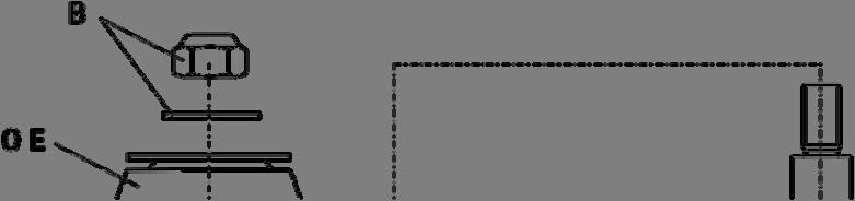
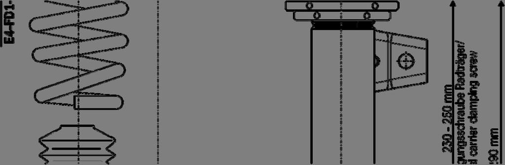
6 Einbauanleitung für Hinterachse - mounting instruction for rear axle Ausbau Das Fahrzeug auf eine radfreie Hebebühne stellen, anheben und Räder demontieren. Die Schräglenker sind beim Ausbau stets mit geeignetem Hilfswerkzeug abzustützen! Die obere und untere Befestigung lösen und entfernen. Den Stoßdämpfer komplett ausbauen und Anbauteile demontieren. Einbau Das Original- Stützlager auf ø 12 mm aufbohren ( s. Skizze Hinterachse ). Die Original Anbauteile entsprechend der Skizze Hinterachse entfernen, mit den BILSTEIN Anbauteilen komplettieren und in umgekehrter Reihenfolge analog zum Ausbau auf den BILSTEIN Stoßdämpfer montieren. Removal Place vehicle on a wheel-free car hoist, lift it and remove wheel The lower control arm must be supported by suitable tools! Remove top and bottom mount. Remove complete shock absorber and original mounting parts. Installation Drill a hole of ø 12 mm into original support bearing ( see rear axle sketch). Remove and modify original mounting parts acc. to the rear axle sketch, complete with BILSTEIN mounting parts and fit on BILSTEIN shock absorber in reverse order as removal. Fit BILSTEIN shock absorber to the vehicle in reverse order as removal. BILSTEIN Stoßdämpfer in umgekehrter Reihenfolge analog zum Ausbau wieder montieren. erstellt am: E4-WM4-Y646A00_4 Seite 6 von 28 geändert am:


7 Hinterachse - rear axle erstellt am: E4-WM4-Y646A00_4 Seite 7 von 28 geändert am:


8 Hinterachs- Höhenverstellung - adjustment assembly rear axle erstellt am: E4-WM4-Y646A00_4 Seite 8 von 28 geändert am:
9 erstellt am: E4-WM4-Y646A00_4 Seite 9 von 28 geändert am:
10 erstellt am: E4-WM4-Y646A00_4 Seite 10 von 28 geändert am:
11 erstellt am: E4-WM4-Y646A00_4 Seite 11 von 28 geändert am:
12 erstellt am: E4-WM4-Y646A00_4 Seite 12 von 28 geändert am:
13 erstellt am: E4-WM4-Y646A00_4 Seite 13 von 28 geändert am:
14 erstellt am: E4-WM4-Y646A00_4 Seite 14 von 28 geändert am:
15 erstellt am: E4-WM4-Y646A00_4 Seite 15 von 28 geändert am:
16 erstellt am: E4-WM4-Y646A00_4 Seite 16 von 28 geändert am:
17 erstellt am: E4-WM4-Y646A00_4 Seite 17 von 28 geändert am:
18 erstellt am: E4-WM4-Y646A00_4 Seite 18 von 28 geändert am:
19 erstellt am: E4-WM4-Y646A00_4 Seite 19 von 28 geändert am:
20 erstellt am: E4-WM4-Y646A00_4 Seite 20 von 28 geändert am:
21 BILSTEIN ridecontrol Lieferumfang Scope of Delivery 1 x Steuergerät ( ST) 1 x Kabelbaum ( KE) 2 m Kabel, braun, 0,75 mm² 2 m Kabel, rot, 0,75 mm² 2 m Kabel, schwarz, 0,75 mm² 3 x Stossverbinder 0,5-1,5 mm² 3 x Kabelabzweigklemmen 0,5-1,5 mm² 3 x Quetschverbinder ø 8,4 mm 3 x Quetschverbinder ø 6,5 mm 1 x LED- Taster ( T) 2 x Kabelverlängerung ( KV) 2,5 m 2 x Kabelverlängerung ( KV) 4,5 m 20 x Kabelbinder erstellt am: E4-WM4-Y646A00_4 Seite 21 von 28 1 x control unit ( ST) 1 x wiring harness ( KE): 2 m wire, brown, 0,75 mm² 2 m wire, red, 0,75 mm² 2 m wire, black, 0,75 mm² 3 x connectors 0,5-1,5 mm² 3 x splice wire clamps 0,5-1,5 mm² 3 x crimping connectors ø 8,4 mm 3 x crimping connectors ø 6,5 mm 1 x LED- switch ( T) 2 x extension cable ( KV) 2,5 m 2 x extension cable ( KV) 4,5 m 20 x tie straps geändert am:
, LED- Taster ( T) für die Bedienung und Kabel ( K) fest ( Achtung! Kann je nach Fahrzeugmodell und Ausstattungsvariante variieren).")
22 Vorbereitungen zur Montage Entfernen Sie im Motorraum die Kunststoffabdeckung im Bereich der Belüftung. Legen Sie die Positionierung des BILSTEIN- Steuergerätes ( ST), LED- Taster ( T) für die Bedienung und Kabel ( K) fest ( Achtung! Kann je nach Fahrzeugmodell und Ausstattungsvariante variieren). Mögliche Positionen sind: ST - rechts außen, am Handschuhfach (Abdeckung muss entfernt werden; siehe Bild 1) Preparations for Installing Remove the plastic cover for cabin ventilation elements at the cowl inside the engine compartment. Determine location for the BILSTEIN control unit ( ST), LED- switch ( T) and for the cables ( K) ( ATTENTION! Location can be different in different vehicles with different equipment). Possible locations are: ST Outside right, next to the glove compartment ( cover must remove; see pic.1) Bild 1/ pic. 1 T - freier Bereich der Alu- oder Kunststoffverkleidung im Armaturenbrett. Entfernung zur Fahrerposition beachten! Die Bedienung während der Fahrt muss gewährleistet sein. - vorne, an der Mittelarmkonsole K - über vorhandene Öffnungen vom Motorraum zur Fahrgastzelle/ über Einstieg/ Seitenverkleidungen der Fahrgastzelle in den Kofferraum Zu beachten ist unbedingt, dass an der ausgewählten Stelle immer ausreichend freier Raum für die Montage zur Verfügung steht und keine vorhandenen Leitungen/ Instrumente im Wege sind. Da nach der Montage ein Zugriff Ihrerseits auf ST nicht mehr notwendig ist, kann er im wesentlichen unsichtbar verbaut werden; es muss allerdings gewährleistet sein, das für die TÜV- Eintragung die Genehmigungsnummer ( e1* ) ablesbar ist!. Für T benötigen Sie eine Bohrung min. ø 18,5 mm. Kabel dürfen nicht über scharfe oder heiße Karosserieteile verlegt werde. Wenn möglich im Fahrzeug vorhandene Leerrohre verwenden. Wählen Sie die Anschlusspunkte so, dass störende Einflüsse auf das elektronische System vermieden werden. Es kann sonst möglicherweise zu Fehlermeldungen und Funktionsstörungen kommen. Die Fixierung und Führung der Kabel erfolgt mit Kabelbinder möglichst an bereits vorhandenen Kabelsträngen. Vermeiden Sie das Aufrollen zu langer Kabel. Es besteht die Gefahr der Selbstinduktion. T Free area of dashboard. Take care that the distance to driver s position is correct! Switch must be accessible to driver when operating the vehicle. Front, at central armrest. K Along existing body holes inside engine bay. Ensure that there is enough free clearance for installation and there are no existing wires/ instruments nearby. ST can be installed in a non-visible location, because there is no need for access after installation; make sure that the type approval number ( e1* ) is readable for TÜV approval or technical inspection! For installation of T a drilled hole of min. ø 18,5 mm / 0.73 is necessary. Take care that all cables do not contact sharp or hot panels. If possible use existing empty conduits. Select connecting points that there is no influence on electronic system. Error messages and malfunction may result. Routing and fastening of cables can be done with tie straps along existing wiring harness. Do not coil extra long cables, as there is danger of self- induction. erstellt am: E4-WM4-Y646A00_4 Seite 22 von 28 geändert am:
23 Montage ( das Steuergerät wurde bei dem Prüffahrzeug im Innenraum platziert) Verkleidung unter dem Armaturenbrett demontieren. Befestigen Sie das BILSTEIN Steuergerät mit Hilfe der beigefügten Klettklebestreifen rechts am Handschuhfach, - Anschlüsse nach oben. Fügen Sie die Steckerverbindung ( SV) von BIL- STEIN Steuergerät ( ST) und Kabelbaum ( KE) zusammen. Der Anschluss der Klemmen KL30, KL15 und KL31 erfolgt mittels mitgelieferter Kabelschuhe am Sicherungskasten ( SK) im Innenraum. Anschließend müssen die Kabel mit entsprechendem Kabelschutz wieder gesichert werden. Die einzelnen Klemmen sind zur besseren Erkennung wie folgt beschriftet. KL 15 KL 30 KL 31 Zündung + Pol - Pol Kabel Kabel Kabel (schwarz) (rot) (braun) Vor dem Anschluss müssen die Klemmen mittels eines Prüfgerätes durchgemessen werden, um fehlerhafte Verbindungen und einen möglichen Kurzschluss zu vermeiden. Kabel anschließend fixieren. Den LED-Taster in die vorher gefertigte Öffnung im Armaturenbrett bzw. der Mittelarmkonsole einsetzten und mit der Kontermutter rückseitig sichern. Das Kabel mit dem Stecker ( SV) für den LED- Taster unter dem Armaturenbrett zum LED-Taster führen. Die Steckerverbindung zwischen LED- Taster und Kabelbaum einclipsen, Kabel fixieren. Kennzeichnung der Kabel zum Anschluss an das jeweilige Federbein/ den Stoßdämpfer ( FB): vorne links - VL/ FL vorne rechts - VR/ FR hinten links - HL/ RL hinten rechts - HR/ RR Das Kabel für VL vom Bilstein Steuergerät durch die Karosserieöffnung (rechts neben der Belüftung), in den Motorraum, unterer der Kunststoffabdeckung (Abdeckung unterhalb der Scheibenwischer), zur linken Fahrzeugseite führen. Durch vorhandene Karosserieöffnungen zum Achsbein führen. Mit dem überstehenden Kabelende des Federbeins verbinden und ausreichend fixieren. Wen nötig, sind die mitgelieferten Kabelverlängerungen (KV 2,5m) zu verwenden. Das Kabel für VR vom Bilstein Steuergerät durch die Karosserieöffnung (rechts neben der Belüftung), in den Motorraum führen. Durch vorhandene Karosserieöffnungen zum Achsbein führen. Mit dem überstehenden Kabelende des Federbeins verbinden und ausreichend fixieren. Installing ( The control unit for our test vehicle was positioned inside passenger compartment) Remove the cover below dashboard. Fasten the BILSTEIN control unit by using supplied Velcro (hook and loop) fastener right next to the glove compartment ports upwards. Connect BILSTEIN control unit ( ST) and wiring harness ( KE) by using the plug ( SV). Connect the terminals ( batt.+, batt.-, ignition) directly with battery pole (batt.+, batt.-) of fuse box ( SK) inside passenger compartment by using delivered cable lugs. Finally all cables must protected with appropriate cover. Each terminal is marked for easy identification as follows: KL 15 ignition wire (black) KL 30 batt.+ wire (red) KL 31 batt.- wire (brown) Check all terminals to avoid short-circuit or defective connection by using a tester before connecting. Fasten wires by using delivered tie straps. Fix the LED button in the previous- made hole in the dashboard or in the center console and secure it with the lock nut from rear side. Guide the cable with the connector ( SV) for the LED button below the dashboard to the button. Connect the plug connection between LED button and cable harness and fix the cable. This is the identification of the cables for connection to the struts / shocks ( FB): front left - VL/ FL - front right - VR/ FR - rear left - HL/ RL - rear right - HR/ RR - Guide the cable for VL from Bilstein control panel through the body opening (right beside of ventilation) into the engine compartment, below the plastic cover (cover below the windshield), lead to the left side of the vehicle and through existing openings to the strut. Connect to the protruding cable end of the strut and fix it sufficiently. If necessary use the supplied extension cables ( KV 2,5 m). Guide the cable for VL from Bilstein control panel through the body opening (right beside of ventilation) into the engine compartment. Lead through existing openings to the strut. Connect to the protruding cable end of the strut and fix it sufficiently. erstellt am: E4-WM4-Y646A00_4 Seite 23 von 28 geändert am:
24 Beide Kabel für die HA vom Bilstein Steuergerät aus, entlang der zuvor geöffneten Einstiegsverkleidung der Beifahrerseite, entlang des Kabelbaums nach hinten führen. Das Kabel für den rechten Stossdämpfer direkt in das Radhaus durch vorhandene Karosserieöffnungen zum Stossdämpfer führen, mit dem überstehenden Kabelende verbinden und ausreichend fixieren. Das Kabel für den linken Stossdämpfer hinter der Rücksitzbank zur linken Fahrzeugseite verlegen, von dort direkt in das Radhaus durch vorhandene Karosserieöffnungen zum Stossdämpfer führen, mit dem überstehenden Kabelende verbinden und ausreichend fixieren. Wenn nötig, sind die mitgelieferten Kabelverlängerungen ( KV 4,5m) zu verwenden. Bedienung Die Bedienung des BILSTEIN ridecontrol erfolgt über den LED- Taster ( T). Sie können zwischen zwei fest eingestellten Stufen wählen: Sport und Komfort. Die Grundeinstellung, also ohne Zuschaltung des BILSTEIN ridecontrol, ist Komfort. Ein Druck auf den LED- Taster schaltet das System in den Modus Sport. Der Aussenring des Tasters und der Punkt in der Mitte leuchten blau. Ein erneuter Druck auf den LED- Taster genügt, um das BILSTEIN ridecontrol wieder zu deaktivieren. Fehleranalyse Der LED- Taster hilft Ihnen auch bei möglicherweise auftretenden Problemen. Ein Blinkcode zeigt an, welches Problem das System stört, sichtbar durch den Punkt in der Mitte des Tasters. Die Blinkdauer und die Pause zwischen dem Blinken beträgt jeweils 1 sec. Nach einer Pause von 3 Sekunden wird der Blinkcode wiederholt. Im Falle einer Fehlermeldung oder eines durch andere Ursachen hervorgerufenen Spannungsverlust wird das BILSTEIN ridecontrol - System automatisch in die Stufe Sport geschaltet. Guide both cables for the rear from Bilstein control panel, along the previously opened footboard at passenger side, along the wiring harness to the backside. The cable for the right shocks lead directly into the wheelhouse through existing body openings to the shock. Connect to the protruding cable end of the shock and fix it sufficiently. Guide the cable for the left shock absorber behind the rear bench seat to the left side of the vehicle. Thence, lead directly into the wheelhouse through existing body openings to the shock. Connect to the protruding cable end of the shock and fix it sufficiently. If necessary use the supplied extension cables ( KV 4,5 m). Operation The BILSTEIN ridecontrol is controlled by the LED- switch ( T). You can select between two settings Comfort and Sport. The base setting is Comfort, with the BILSTEIN ridecontrol switched off. Push the LED- switch to switch the system on (firm) The outer race and a spot in the middle of the switch illuminates blue. Push the LED- switch again to switch the BIL- STEIN ridecontrol off (soft). Error Analysis The LED switch assists you in case problems occur. A blink code, visualized by the spot in the middle of the switch, indicates which problem is preventing an optimal function of the system. Blink duration and pause between the blinks is 1 sec. After a 3 sec. pause the blink code starts again. In case of error message or power failure for any other reason, the BILSTEIN ridecontrol is set to Sport automatically. erstellt am: E4-WM4-Y646A00_4 Seite 24 von 28 geändert am:
25 Code Kein/ none Fehler/ Error keine Anzeige, System außer Funktion/ no blink, system out of order Energieversorgung System/ system power supply Dämpfer vorne links n. i. O/ shock absorber front left fault. Dämpfer vorne rechts n.i.o/ shock absorber front right fault. Dämpfer hinten links n.i.o/ shock absorber rear left fault. mögliche Lösung/ solutions Sicherung prüfen Spannung KL15 (Zündstrom) und KL 30 (Batteriespannung) prüfen KL 31 (Masse) prüfen Sicherung prüfen Spannung KL 15 (Zündstrom) und KL 30 (Batteriespannung) prüfen KL 31 (Masse) prüfen Sichtkontrolle Kabel/ Stecker Steckverbindung Kabelbaum/ Kabelverlängerung VL/ FL trennen. Stecker der Kabelverlängerung auf Durchgang prüfen. Widerstandwert zu hoch = Unterbrechung im System; Widerstandwert zu niedrig= Kurzschluss im System Prüfung wie zuvor an der Kabelverlängerung/ Stoßdämpfer wiederholen. Sichtkontrolle Kabel/Stecker Steckverbindung Kabelbaum/ Kabelverlängerung VR/ FR trennen. Stecker der Kabelverlängerung auf Durchgang prüfen. Widerstandwert zu hoch = Unterbrechung im System; Widerstandwert zu niedrig= Kurzschluss im System Prüfung wie zuvor an der Kabelverlängerung/ Stoßdämpfer wiederholen. Sichtkontrolle Kabel/Stecker Steckverbindung Kabelbaum/ Kabelverlängerung HL/ RL trennen. Stecker der Kabelverlängerung auf Durchgang prüfen. Widerstandwert zu hoch = Unterbrechung im System; Widerstandwert zu niedrig= Kurzschluss im System Prüfung wie zuvor an der Kabelverlängerung/ Stoßdämpfer wiederholen. check fuse check voltage KL15 (ignition voltage) and KL30 (battery voltage) check KL31 (ground) check fuse check voltage KL15 (ignition voltage) and KL30 (battery voltage) check KL31 (ground) visually check cable/ plugs disconnect plugs between wiring harness and extension cables VL/ FL. Check plugs of extension cable for continuity. Resistance high = open circuit in system Resistance low = short circuit in system same check as above, at plugs between extension cable and strut visually check cable/ plugs disconnect plugs between wiring harness and extension cables VR/ FR. Check plugs of extension cable for continuity. Resistance high = open circuit in system Resistance low = short circuit in system same check as before, at plugs between extension cable and strut visually check cable/ plugs disconnect plugs between wiring harness and extension cables HL/ RL. Check plugs of extension cable for continuity. Resistance high = open circuit in system Resistance low = short circuit in system same check as before, at plugs between extension cable and strut Sollwerte/ Control input 6,8-16 Volt 6,8-16 Volt 5,6 ±0,4 Ohm 5,6 ±0,4 Ohm 5,6 ±0,4 Ohm 5,6 ±0,4 Ohm 5,6 ±0,4 Ohm 5,6 ±0,4 Ohm erstellt am: E4-WM4-Y646A00_4 Seite 25 von 28 geändert am:
26 5 6 7 Dämpfer hinten rechts n.i.o/ shock absorber rear right fault Interner Steuergeräte Fehler/ internal controller error Bedieneinheit (LED-Taster) n.i.o./ Control Unit ( LED button) fault Sichtkontrolle Kabel/Stecker visually check cable/ plugs Steckverbindung Kabelbaum/ Kabelverlängerung HR/ RR trennen. harness and extension cables HR/ disconnect plugs between wiring Stecker der Kabelverlängerung auf RR. Check plugs of extension cable Durchgang prüfen. for continuity. 5,6 ±0,4 Ohm Widerstandwert zu hoch = Unterbrechung im System; system Resistance high = open circuit in Widerstandwert zu niedrig= Kurzschluss im System system Resistance low = short circuit in Prüfung wie zuvor an der Kabelverlängerung/ Stoßdämpfer wiederholen. between extension cable and strut same check as before, at plugs 5,6 ±0,4 Ohm Bitte setzen Sie sich mit Ihrem Please contact your BILSTEIN BILSTEIN- Service in Verbindung! Service Partner! Steckverbindung LED- Taster/ Steuergerät trennen. Durchgangsmessungen der Kabel ge- and control unit. Check continuity Disconnect plugs of LED- switch geneinander durchführen. among cables. KL 15 Zündstrom gegen gelb KL 15 ignition current vs. yellow 100 Ohm KL 15 Zündstrom gegen grün KL 15 ignition current vs. green Ohm KL 15 Zündstrom gegen grau KL 15 ignition current vs. grey Ohm KL 15 Zündstrom gegen KL 31 KL 15 ignition current vs. KL 31 Ohm erstellt am: E4-WM4-Y646A00_4 Seite 26 von 28 geändert am:


 wire (black) wire")

27 Legende 1-1stlegend KL 15 Zündung KL 30 + Pol KL 31 - Pol KL 15 ignition KL 30 batt.+ KL 31 batt.- Kabel (schwarz) Kabel (rot) Kabel (braun) wire (black) wire (red) wire (brown) erstellt am: E4-WM4-Y646A00_4 Seite 27 von 28 geändert am:
28 ThyssenKrupp Bilstein GmbH Milsper Straße 214; D Ennepetal Postfach 1151, D Ennepetal Phone: Fax: erstellt am: E4-WM4-Y646A00_4 Seite 28 von 28 geändert am:
Inhalt : - Teile- Gutachten. - Einbauanleitungen. Contents: Certificate - RENAULT Clio 3 RS (R) B14 - Mounting instruction -
 B14 - Mounting instruction -") Inhalt : - Teile- Gutachten - RENAULT Clio 3 RS (R) B14 - Einbauanleitungen Contents: Certificate - RENAULT Clio 3 RS (R) B14 - Mounting instruction - erstellt am:12.01.15 E4-WM4-Y696A00_0 Seite 1 von
Inhalt : - Teile- Gutachten - RENAULT Clio 3 RS (R) B14 - Einbauanleitungen Contents: Certificate - RENAULT Clio 3 RS (R) B14 - Mounting instruction - erstellt am:12.01.15 E4-WM4-Y696A00_0 Seite 1 von
Inhalt : Contents: - certificate for: W 204 B14 and B16 PSS10 - W 204 AMG B14 and B16 PSS10 - S 204 station wagon AMG B14 and B16 PSS10 -
 Inhalt : - Teile- Gutachten für: - W 204 B14 und B16 PSS10 - W 204 AMG B14 und B16 PSS10 - S 204 Kombi B14 und B16 PSS10 - S 204 Kombi AMG B14 und B16 PSS10 - W 207 Coupe und Cabrio B14 und B16 PSS10 -
Inhalt : Contents: - certificate for:
 Inhalt : - Teile- Gutachten für: - VW Beetle B14/ B16 PSS10 (nur für Fahrzeuge mit Mehrlenker Hinterachse) - VW Golf VI B14/ B16 PSS10 - VW Scirocco B14/ B16 PSS10 - Einbauanleitungen Contents: - certificate
- certificate BILSTEIN ridecontrol for:
 Inhalt : - Teile- Gutachten BILSTEIN ridecontrol - AUDI A4 ( B8) Limousine/ Avant - AUDI A5 ( B8) Coupe - AUDI S5 ( B8) Coupe - Einbauanleitungen Contents: - certificate BILSTEIN ridecontrol for: AUDI
Inhalt : - Teile- Gutachten BILSTEIN ridecontrol - AUDI A4 ( B8/B81) Limousine/ Avant - AUDI RS4 ( B8/B81) Limousine/ Avant
 Limousine/ Avant - AUDI RS4 ( B8/B81) Limousine/ Avant") Inhalt : - Teile- Gutachten BILSTEIN ridecontrol - AUDI A4 ( B8/B81) Limousine/ Avant - AUDI S4 ( B8/B81) Limousine/ Avant - AUDI RS4 ( B8/B81) Limousine/ Avant - AUDI A5 ( B8/B81) Limousine/ Avant - AUDI
Inhalt : - Teile- Gutachten BILSTEIN ridecontrol - AUDI A4 ( B8/B81) Limousine/ Avant - AUDI S4 ( B8/B81) Limousine/ Avant - AUDI RS4 ( B8/B81) Limousine/ Avant - AUDI A5 ( B8/B81) Limousine/ Avant - AUDI
- inklusiv X-Drive. - Einbauanleitungen. Contents: - Certificate ( removable) for:
 for:") Inhalt : - Teile- Gutachten für: ( herausnehmbar) - BMW 1er (F20/F21) B16 BRC - BMW 2er (F22) B16 BRC - BMW 3er (F30/F31) B16 BRC - BMW 4er (F32/F33) B16 BRC - inklusiv X-Drive - Einbauanleitungen Contents:
Inhalt : - Teile- Gutachten für: ( herausnehmbar) - BMW 1er (F20/F21) B16 BRC - BMW 2er (F22) B16 BRC - BMW 3er (F30/F31) B16 BRC - BMW 4er (F32/F33) B16 BRC - inklusiv X-Drive - Einbauanleitungen Contents:
- BILSTEIN Clubsport Certificate for:
 Inhalt : - BILSTEIN Clubsport Teile- Gutachten für: - Mercedes Benz C-Klasse (W204) AMG (ohne Black Series) - Einbauanleitungen Contents: - BILSTEIN Clubsport Certificate for: Mercedes Benz C-class (W204)
Inhalt: - Teile- Gutachten für: ( herausnehmbar) - RENAULT Clio II V. - Einbauanleitungen. - englischer Anhang. Contents:
 - RENAULT Clio II V. - Einbauanleitungen. - englischer Anhang. Contents:") Inhalt: - Teile- Gutachten für: ( herausnehmbar) - RENAULT Clio II 2.0 16V - Einbauanleitungen - englischer Anhang Contents: - certificate ( removable) for: - RENAULT Clio II 2.0 16V - mounting instruction
Inhalt: - Teile- Gutachten für: ( herausnehmbar) - RENAULT Clio II 2.0 16V - Einbauanleitungen - englischer Anhang Contents: - certificate ( removable) for: - RENAULT Clio II 2.0 16V - mounting instruction
BMW E 63 coupe BMW E 64 convertible
 BMW E 63 coupe BMW E 64 convertible Hinweis für die Kraftverstellung - instructions for force adjustment Verstellposition 9 = weich ( im Uhrzeigersinn drehen ) Verstellposition 1 = hart ( gegen Uhrzeigersinn
- Certificate ( removable) for:
 for:") Inhalt : - Teile- Gutachten für: ( herausnehmbar) - AUDI A4 ( B5) Limousine/ Avant - Einbauanleitungen - englischer Anhang Contents: - Certificate ( removable) for: AUDI A4 ( B5) sedan/ station wagon -
Inhalt : - Teile- Gutachten für: ( herausnehmbar) - AUDI A4 ( B5) Limousine/ Avant - Einbauanleitungen - englischer Anhang Contents: - Certificate ( removable) for: AUDI A4 ( B5) sedan/ station wagon -
Inhalt: - Teile- Gutachten für: ( herausnehmbar) - Smart Fortwo Coupe ab 03.01 - Smart Fortwo Cabrio ab 03.01 - Smart Roadster - Smart Coupe
 - Smart Fortwo Coupe ab 03.01 - Smart Fortwo Cabrio ab 03.01 - Smart Roadster - Smart Coupe") Inhalt: - Teile- Gutachten für: ( herausnehmbar) - Smart Fortwo Coupe ab 03.01 - Smart Fortwo Cabrio ab 03.01 - Smart Roadster - Smart Coupe - Einbauanleitungen - englischer Anhang Contents: - certificate
Inhalt: - Teile- Gutachten für: ( herausnehmbar) - Smart Fortwo Coupe ab 03.01 - Smart Fortwo Cabrio ab 03.01 - Smart Roadster - Smart Coupe - Einbauanleitungen - englischer Anhang Contents: - certificate
Inhalt : - Teile- Gutachten für: - Mercedes Benz SLK W170 - CHRYSLER Crossfire Coupe - CHRYSLER Crossfire Roadster. Contents: - certificate for:
 Inhalt : - Teile- Gutachten für: - Mercedes Benz SLK W170 - CHRYSLER Crossfire Coupe - CHRYSLER Crossfire Roadster - Einbauanleitungen - englischer Anhang Contents: - certificate for: Mercedes Benz SLK
RS232-Verbindung, RXU10 Herstellen einer RS232-Verbindung zwischen PC und Messgerät oder Modem und Messgerät
 Betriebsanleitung RS232-Verbindung, RXU10 Herstellen einer RS232-Verbindung zwischen PC und Messgerät oder Modem und Messgerät ä 2 Operating Instructions RS232 Connection, RXU10 Setting up an RS232 connection
CABLE TESTER. Manual DN-14003
 CABLE TESTER Manual DN-14003 Note: Please read and learn safety instructions before use or maintain the equipment This cable tester can t test any electrified product. 9V reduplicated battery is used in
Installation Instructions
 EN DE Installation Instructions WLAN Installation Kit, 300 Mbps, 5 GHz, 16 dbi AK-4 Wireless Kit Scope of delivery Junction box AK-4 (1x) 1 Connection board AK-4 CB with 12VDC power supply unit (1x) 2
Parameter-Updatesoftware PF-12 Plus
 Parameter-Updatesoftware PF-12 Plus Mai / May 2015 Inhalt 1. Durchführung des Parameter-Updates... 2 2. Kontakt... 6 Content 1. Performance of the parameter-update... 4 2. Contact... 6 1. Durchführung
HPS.04.696.10000/B Revision: 01. Hauptständer KTM 990 SM-T / SM-R '09 Center Stand KTM 990 SM-T / SM-R '09
 Hauptständer KTM 0 SM-T / SM-R '0 Center Stand KTM 0 SM-T / SM-R '0 Montagehinweise Revision: 01 Mounting Instruction Achtung: Die Kurven- und Bodenfreiheit kann durch einen Hauptständer eingeschränkt
Installation manual / Montageanleitung WBC2 splice patch with Fibertray Spleissung/Rangierung mit Fibertray
 Content of Assembly Instruction I. Required tools II. Required parts III. Installation Inhalt der Montageanleitung I. Benötigte Werkzeuge II. Benötigte Teile III. Installation I. Required tools: I. Benötigtes
TomTom WEBFLEET Tachograph
 TomTom WEBFLEET Tachograph Installation TG, 17.06.2013 Terms & Conditions Customers can sign-up for WEBFLEET Tachograph Management using the additional services form. Remote download Price: NAT: 9,90.-/EU:
Nachdem Sie die Datei (z.b. t330usbflashupdate.exe) heruntergeladen haben, führen Sie bitte einen Doppelklick mit der linken Maustaste darauf aus:
 heruntergeladen haben, führen Sie bitte einen Doppelklick mit der linken Maustaste darauf aus:") Deutsch 1.0 Vorbereitung für das Firmwareupdate Vergewissern Sie sich, dass Sie den USB-Treiber für Ihr Gerät installiert haben. Diesen können Sie auf unserer Internetseite unter www.testo.de downloaden.
Deutsch 1.0 Vorbereitung für das Firmwareupdate Vergewissern Sie sich, dass Sie den USB-Treiber für Ihr Gerät installiert haben. Diesen können Sie auf unserer Internetseite unter www.testo.de downloaden.
p^db=`oj===pìééçêíáåñçêã~íáçå=
 p^db=`oj===pìééçêíáåñçêã~íáçå= Error: "Could not connect to the SQL Server Instance" or "Failed to open a connection to the database." When you attempt to launch ACT! by Sage or ACT by Sage Premium for
torqeedo heckmotorhalterung stern-motor-bracket holiday/explorer Riverstar, adventure
 torqeedo heckmotorhalterung stern-motor-bracket holiday/explorer Riverstar, adventure MONTAGEANLEITUNG Assembly instructions Besitzer/Name: Owner/name: PLZ, Ort: Post code, town: Straße, Nr.: Street, nr:
Deutsch: REPARATURANWEISUNG
 DE: Diese Anweisung ist in zwei Sprachen verfügbar. ENG: This instruction is available in two languages. Deutsch: REPARATURANWEISUNG English: REPAIR INSTRUCTION Dok.-Nr. RA L4.00-00 Sprachen-2-Deckblatt
Cable Tester NS-468. Safety instructions
 Cable Tester NS-468 Safety instructions Do not use the cable tester NS-468 if it is damaged. This device is only for use inside dry and clean rooms. This device must be protected from moisture, splash
FOX EXHAUST SYSTEMS//
 FOX EXHAUST SYSTEMS// MONTAGEANLEITUNG V2397/ V2398 Opel Adam ENDSCHALLDÄMPFER/ VORSCHALLDÄMPFER Artikelnummer: OP210005-xxx / OP210000-VSD 1. Lieferumfang: 1x 1x 1x 1xVerbindungsrohr 2 1xVerbindungsrohr
Hazards and measures against hazards by implementation of safe pneumatic circuits
 Application of EN ISO 13849-1 in electro-pneumatic control systems Hazards and measures against hazards by implementation of safe pneumatic circuits These examples of switching circuits are offered free
Installation guide for Cloud and Square
 Installation guide for Cloud and Square 1. Scope of delivery 1.1 Baffle tile package and ceiling construction - 13 pcs. of baffles - Sub construction - 4 pcs. of distance tubes white (for direct mounting)
FIRMWARE UPDATE TAPMOTION TD
 FIRMWARE UPDATE TAPMOTION TD CMP-SPF TO WHOM IT MAY CONCERN Seite 1 von 9 Inhalt / Overview 1. Firmware überprüfen und Update-file auswählen / Firmware check and selection of update file 2. Update File
!!! UNBEDINGT BEACHTEN!!!
 Produktinformation 201501_197PAdeen Deutsch Seite 1 5 English page 6 10 Solldaten-Update Achsvermessung 2015 WA 900 / 920 / 020 / 950 / 970 CURA S 800 / 860 / 060 / 900 / 960 WAB01 / WAB 02 CCT / RoboLigner
Installation manual for Conen height adjustable pylon systems for interactive whiteboards Montageanleitung für Conen höhenverstellbare Pylonensysteme
 Installation manual for Conen height adjustable pylon systems for interactive whiteboards Montageanleitung für Conen höhenverstellbare Pylonensysteme für interaktive Whiteboards 1. Introduction Einleitung
Schutzart IP 20 protection degree IP 20 18
 MODUL L 196 Pendelleuchte / suspended luminaire MONTAGE / MOUNTING 010-614. 009-282. 010-095 direktstrahlend / direct beam 010-613. 009-281. 010-094 mit Indirektlichtanteil / with indirect light component
User Manual Bedienungsanleitung. www.snom.com. snom Wireless Headset Adapter snom Schnurlos-Headset-Adapter. English. Deutsch
 English snom Wireless Headset Adapter snom Schnurlos-Headset-Adapter Deutsch User Manual Bedienungsanleitung 2007 snom technology AG All rights reserved. Version 1.00 www.snom.com English snom Wireless
Mast- / Wandmontage Kit Einbauanleitung Pole- / Wallmount Kit Installation Guide
 Alpha ATROX Mast- / Wandmontage Kit Einbauanleitung Pole- / Wallmount Kit Installation Guide Ihr Partner für Energieversorgungslösungen Mast- und Wandmontage Kit Alpha ATROX Pole- and Wall Mount Kit Alpha
Installation manual for Conen height adjustable spring tension mechanism for interactive whiteboards Montageanleitung für Conen höhenverstellbare
 Installation manual for Conen height adjustable spring tension mechanism for interactive whiteboards Montageanleitung für Conen höhenverstellbare Federzugsysteme für interaktive Whiteboards 1. Introduction
FOX EXHAUST SYSTEMS//
 FOX EXHAUST SYSTEMS// MONTAGEANLEITUNG V1106 Renault Clio II ENDSCHALLDÄMPFER Artikelnummer: RE071022-xxx 1. Lieferumfang: 1x 1x M8 1x 1xHaltegummi 1xM8x25 1x 58,5mm 1x48,5mm 1x43,5mm 1x Ø9mm 1xZusatzhalter
UWC 8801 / 8802 / 8803
 Wandbedieneinheit Wall Panel UWC 8801 / 8802 / 8803 Bedienungsanleitung User Manual BDA V130601DE UWC 8801 Wandbedieneinheit Anschluss Vor dem Anschluss ist der UMM 8800 unbedingt auszuschalten. Die Übertragung
Technische Dokumentation Technical Documentation. Adventure A10
 Ulrich Alber GmbH Vor dem Weißen Stein 21 D-72461 Albstadt-Tailfingen Telefon (07432) 2006-0 Telefax (07432) 2006-279 email info@alber.de home www.alber.de 50.0025.2.99.01 Technische Dokumentation Technical
KURZANLEITUNG. Firmware-Upgrade: Wie geht das eigentlich?
 KURZANLEITUNG Firmware-Upgrade: Wie geht das eigentlich? Die Firmware ist eine Software, die auf der IP-Kamera installiert ist und alle Funktionen des Gerätes steuert. Nach dem Firmware-Update stehen Ihnen
Schnell-Start-Anleitung Quick Start Guide
 Schnell-Start-Anleitung Quick Start Guide 3 1. Cube anschließen Schließen Sie den Cube an die Stromversorgung an. Verbinden Sie den Cube mit dem Router. Die Power- und die Internet-LED beginnen zu blinken,
M90/60 Spare Parts Catalog SPC-M90-01
 1 M90/60 Spare Parts Catalog SPC-M90-01 Notice: i. The Spare Parts prices are subject to change without notice. ii. The Spare Parts & Assembly Groups are subject to change without notice. iii. The drawings
CAN-Bus RPM adapter. User Manual Anwender-Beschreibung
 CAN-Bus RPM adapter COT02 User Manual Anwender-Beschreibung Stand: 12.02.03 GRABAU Computertechnik GmbH Elsener Str. 30 33102 Paderborn Tel: +49 5251 1367-0 Fax: +49 5251 1367-30 Email: info@grabau.de
Schutzart IP 20 protection degree IP 20 18
 MODUL L 196 Pendelleuchte / suspended luminaire MONTAGE / MOUNTING 010-614. 009-282. 010-095 24 V DC / 40 W 010-613. 009-281. 010-094 24 V DC / 45 W Schutzart IP 20 protection degree IP 20 18 max. 1500
 Information & Montageanleitung Information & Mounting instructions lassic Performance Premium 90 mm Module Halogen H7 12V ES / 1BL 009 999-... LES / EE 1ML 009 999-... US / SAE 1BL 009 999-... 24V ES /
Please do not use in live circuits. When the POWER LED does not light, you must change the battery for testing.
 L A N / U S B C A B L E T E S T E R I n s t a l l a t i o n 1 2 9 9 6 4 1. I n t r o d u c t i o n The LAN/USB Cable Tester is designed to easily read the correct cable pin out configuration. The cables
INSTALLATION AND OPERATING INSTRUCTIONS FOR LPS203-M LPS203-M 操 作 指 示
 BEDIENUNGSANLEITUNG To comply with the published safety standards, the following must be observed when using this power supply. Um den zur Zeit gültigen Sicherheitsbestimmungen zu genügen, müssen die nachstehenden
Thermalright. Macho 120
 Thermalright Macho 120 Macho 120 Assembly package 4 1 4 4 4 7 5 4 4 4 1 Chill Factor 1 1 2 1 8 Macho 120 Intel 775/1155/1156/1366 Exploded View Important! Before proceeding with installation, please check
Order Number Bestellnummer. Hand crimp tool Handcrimpzange Positioner Einsatz Positioner Einsatz. Order Number. Bestellnummer
 Crimpingtools for Miniature Connectors Crimpwerkzeuge für Miniatursteckverbinder Hand Crimp Tool M22520/2-01 for Machined Contacts Handcrimpzange M22520/2-01 für gedrehte Kontakte Die / Einsatz Hand crimp
Batterie-Identifikations-Modul EL-BIM
 Bedienungs- und Montageanleitung Batterie-Identifikations-Modul EL-BIM 1.0 Allgemeines Das Batterie-Identifikations-Modul EL-BIM ermöglicht eine eindeutige Zuordnung von Ladevorgang und Batterie in den
ReadMe zur Installation der BRICKware for Windows, Version 6.1.2. ReadMe on Installing BRICKware for Windows, Version 6.1.2
 ReadMe zur Installation der BRICKware for Windows, Version 6.1.2 Seiten 2-4 ReadMe on Installing BRICKware for Windows, Version 6.1.2 Pages 5/6 BRICKware for Windows ReadMe 1 1 BRICKware for Windows, Version
Outdoor Netzteil 24 VAC Installationsanleitung
 Outdoor Netzteil 24 VAC Installationsanleitung Version 1.0 (09/2009) TV8379 1. Vorwort Sehr geehrte Kundin, sehr geehrter Kunde, wir bedanken uns für den Kauf dieses 24VAC Outdoor Netzteils. Mit diesem
roll-up SONJA powerdisplays Aufbauanleitung Assemble instructions
 powerdisplay SONJA Mit Rollfunktion! Die Werbefläche rollt sich vollständig in das Display. So ist Ihre Werbung geschützt und in Sekunden wieder aufgebaut. Farbe: chrom/silber inkl. Tasche With rolling
NEWSLETTER. FileDirector Version 2.5 Novelties. Filing system designer. Filing system in WinClient
 Filing system designer FileDirector Version 2.5 Novelties FileDirector offers an easy way to design the filing system in WinClient. The filing system provides an Explorer-like structure in WinClient. The
Beipackzettel Instruction leaflet
 Beipackzettel Instruction leaflet Montage an einen Wandarm Mounting to wall arm Pepperl+Fuchs GmbH Antoniusstr. 21 D-73249 Wernau Germany Tel.: +49(0) 621 776-3712 Fax: +49(0) 621 776-3729 www.pepperl-fuchs.com
KW st reet comfor t MEHR KOMFORT UND SPORTLICHE PERFORMANCE WEIL KEIN WIDERSPRUCH SIND! SPORTY PERFORMANCE ARE BECAUSE MORE COMFORT AND
 KW st reet comfor t Dynamik, Komfort und tolle Optik das bietet für mich nur die überlegene Technik von KW Street Comfort. Dynamic, comfort and a great look this is what the superior technology from KW
ALL1681 Wireless 802.11g Powerline Router Quick Installation Guide
 ALL1681 Wireless 802.11g Powerline Router Quick Installation Guide 1 SET ALL1681 Upon you receive your wireless Router, please check that the following contents are packaged: - Powerline Wireless Router
Service Manual Kugelgelenke an DT Swiss Dämpfer ersetzen Replace spherical bearings on DT Swiss shocks
 Service Manual Kugelgelenke an DT Swiss Dämpfer ersetzen Replace spherical bearings on DT Swiss shocks www.dtswiss.com - Inhaltsverzeichnis / Table of contents Einleitung... 2 Instructions... 2 Montage
MU-307 A SAFETY INSTRUCTIONS SICHERHEITSHINWEISE FEATURES MERKMALE
 SAFETY INSTRUCTIONS Read all safety instruction before operating the amplifiers. 1. Install equipment as follow condition: - Install at flat place, not bending curved. - Do not install near the water and
Cameraserver mini. commissioning. Ihre Vision ist unsere Aufgabe
 Cameraserver mini commissioning Page 1 Cameraserver - commissioning Contents 1. Plug IN... 3 2. Turn ON... 3 3. Network configuration... 4 4. Client-Installation... 6 4.1 Desktop Client... 6 4.2 Silverlight
Westfalia Bedienungsanleitung. Nr
 Bedienungsanleitung Nr. 107375 Bedienungsanleitung Satelliten Finder RL-TC-0101 Artikel Nr. 54 25 97 Instruction Manual Satellite Finder RL-TC-0101 Article No. 54 25 97 Benutzung Funktionsumfang Regelbare
Produktinformation Access Upgrade Video. Product information Access licence for video upgrade AUV 870-0 T AUV 870-0 F
 Produktinformation Access Upgrade Video Product information Access licence for video upgrade AUV 870-0 T AUV 870-0 F 1+2 100-1216 V1.1.2 1216-11-1159 MAC-Adresse D4-E3-2C-XX-XX-XX 3+4 press click 2 5 6
1. Allgemeine Information
 1. Allgemeine Information ACHTUNG! Der Betriebsdruck der Klasse 876 ist 6 bar. Sollte der Druck Ihrer Versorgungsleitung höher als 6 bar sein, muss der Druck an der Versorgungseinheit der Nähmaschine auf
Software-Update Version 1.0.10 manual. In order to keep your door systems updated, please proceed with the following changes.
 Software-Update Version 1.0.10 manual In order to keep your door systems updated, please proceed with the following changes. 1. Exchange CPU -Z1 (E60-0228-10) by the new one you already received. Front
Cisco SSPA122. Installation und manuelle Rekonfiguration. Dokumentenversion 1
 Cisco SSPA122 Installation und manuelle Rekonfiguration Dokumentenversion 1 Placetel UC-One Cisco SPA122 Installation und manuelle Rekonfiguration Copyright Hinweis Copyright 2015 finocom AG Alle Rechte
Art.-Nr. 4450900300 greentea. Art.-Nr. 4450900200 whitemusk MAGICUS. 1 Stück/piece 2,5. 4 x 4 x 4 x. 1 x
 MAGICUS Art.-Nr. 4450900300 greentea 1 Stück/piece Art.-Nr. 4450900200 whitemusk 2,5 4 x 4 x 4 x 1 x 1. 2. 1 x Option 2 Option 1 3. 1 3 4 2 4. I AUTO RUN Mo Tu We Th Fr Sa Su OK + Clear R 230VAC, 50Hz
Worx Landroid - Software Update
 Worx Landroid - Software Update WORX Landroid Software Update für Anwender 30.04.2015 Website: www.worxlandroid.com Direct Direkter Link Link for auf the Update: Update: https://www.worxlandroid.com/en/software-update
Hör auf zu ziehen! Erziehungsleine Training Leash
 Hör auf zu ziehen! Erziehungsleine Training Leash 1 2 3 4 5 6 7 Erziehungsleine Hör auf zu ziehen Ihr Hund zieht an der Leine, und Sie können ihm dieses Verhalten einfach nicht abgewöhnen? Die Erziehungsleine
Fleet Manager 100 Bedienungsanleitung User Manual Hardware
 Bedienungsanleitung User Manual Hardware 1. Bedienung im Fahrzeug... 2 2. Signale des Bordcomputers (LED, Summer)... 4 3. Fehlersuche... 5 1. Operation in the vehicle... 7 2. Buzzer codes... 9 3. Troubleshooting...
spare parts for Mercedes Benz
 spare parts for 02/2013 Achse / Axle 63 451 424 BOOT KIT W 123 W 126 126 350 03 37 63 451 425 BOOT KIT W 140 140 350 11 37 63 451 426 BOOT KIT 210 357 00 91 210 357 01 91 11 000 007 ENGINE MOUNTING 124
5 TFT LCD MONITOR LCM 1250 BEDIENUNG / OPERATION AUF DEN BILDSCHIRM SEHEN! DON T WATCH AND DRIVE!
 5 TFT LCD MONITOR LCM 1250 BEDIENUNG / OPERATION ACHTUNG FAHRER! CAUTION! NICHT WÄHREND DER FAHRT AUF DEN BILDSCHIRM SEHEN! DON T WATCH AND DRIVE! Sicherheitshinweise 1. Achten Sie darauf, dass durch die
Aufgabenstellung Mit welchen SICLOCK Produkten kann ich einen PC Zeitsynchronisieren?
 SICLOCK Application Note AN-0005 Titel Synchronisation von PCs mit SICLOCK Aufgabenstellung Mit welchen SICLOCK Produkten kann ich einen PC Zeitsynchronisieren? Schlüsselwörter SICLOCK DCFRS, WinGPS, GPS1000,
Bedienungsanleitung / User Manual. PAR 56 RGB LED PAR 64 RGB LED (183x10mm LED s) mit 5 DMX Kanälen/ with 5 DMX channles
 mit 5 DMX Kanälen/ with 5 DMX channles") Bedienungsanleitung / User Manual PAR 56 RGB LED PAR 64 RGB LED (183x10mm LED s) mit 5 DMX Kanälen/ with 5 DMX channles Inhalt 1 Sicherheitsbestimmungen... 3 2 Übersicht... 3 3 Funktionen... 4 3.1 Automatischer
Bedienungsanleitung / User Manual PAR 56 RGB LED PAR 64 RGB LED (183x10mm LED s) mit 5 DMX Kanälen/ with 5 DMX channles Inhalt 1 Sicherheitsbestimmungen... 3 2 Übersicht... 3 3 Funktionen... 4 3.1 Automatischer
FLACHSICHERUNGSDOSEN BLADE FUSE BOXES
 FLACHSICHERUNGSDOSEN ES Flachsicherungsdosen 15 00 00 und Varianten Die Flachsicherungsdosen und Zentralstecker gibt es in zwei-, vier-, sechs- und achtpoliger Ausführung und in den Farben schwarz, natur,
Produktinformation 201407_182PNdeen
 Produktinformation 201407_182PNdeen Deutsch Seite 1-2 English page 3 4 Produkt Information POWER LIFT HL 2.35 NT DT Fahrzeuge und Transporter werden immer schwerer, von der Automobilindustrie und den Autohäusern
EMCO Installationsanleitung Installation instructions
 EMCO Installationsanleitung Installation instructions Installationsanleitung Installation instructions Digitalanzeige digital display C40, FB450 L, FB600 L, EM 14D/17D/20D Ausgabe Edition A 2009-12 Deutsch...2
Ersatzteil-Katalog / Spare Parts Catalogue 24V
 Ersatzteil-Katalog / Spare Parts Catalogue 24V Stand: 31. Juli 2009 Inhaltsverzeichnis / content: Kontaktbelegungsplan / wiring diagramm Heckleuchten / rear lights Europoint II Europoint I Ecopoint II
Montageanleitung / Mounting Instructions. CELSIUS M / R / V / W Rack Kit
 Montageanleitung / Mounting Instructions System CELSIUS M / R / V / W Rack Kit Congratulations on your purchase of an innovative product from Fujitsu. The latest information about our products, tips, updates
E asyline by Hama GmbH & Co KG Postfach 80 86651 Monheim/Germany Tel. +49 (0)9091/502-0 Fax +49 (0)9091/502-274 hama@hama.de www.hama.
9091/502-0 Fax +49 (0)9091/502-274 hama@hama.de www.hama.") 00021024-10.06 E asyline by Hama GmbH & Co KG Postfach 80 86651 Monheim/Germany Tel. +49 (0)9091/502-0 Fax +49 (0)9091/502-274 hama@hama.de www.hama.com Gamepad Thunderstorm II 0021024 l Bedienungsanleitung
00021024-10.06 E asyline by Hama GmbH & Co KG Postfach 80 86651 Monheim/Germany Tel. +49 (0)9091/502-0 Fax +49 (0)9091/502-274 hama@hama.de www.hama.com Gamepad Thunderstorm II 0021024 l Bedienungsanleitung
Weitere Hinweise, siehe Einbaubeispiele S.46! More notes on the installation example P. 46 Reedschalter Kabel 2m Reed switch cable 2m
 Reedschalter T-Typ Reed switch T- type 6.5 29.5 5.5 1 eingebauten Permanentmagneten wird der The Reed-switch will be operated by the magnetic field of the permanent magnets inside the yoke. Weitere Hinweise,
Quick Start Guide RED 10
 Quick Start Guide RED 10 Sophos Access Points 1. Preparation Note: Before you begin, please make sure that you have a working Internet connection. Congratulations on your purchase of the Sophos RED security
p^db=`oj===pìééçêíáåñçêã~íáçå=
 p^db=`oj===pìééçêíáåñçêã~íáçå= How to Disable User Account Control (UAC) in Windows Vista You are attempting to install or uninstall ACT! when Windows does not allow you access to needed files or folders.
Interconnection Technology
 Interconnection Technology Register: 23 Date: 25.05.99 Measuring leads from Hirschmann Following measuring leads are replaced by the next generation. Additionally connectors and sockets in the same design
Kuhnke Technical Data. Contact Details
 Kuhnke Technical Data The following page(s) are extracted from multi-page Kuhnke product catalogues or CDROMs and any page number shown is relevant to the original document. The PDF sheets here may have
- FOR USE IN AIRCRAFT -
 Qualification Organisation LF/C/013/11 EXT2 Grant / Extension of a - FOR USE IN AIRCRAFT - Qualification Mark. Valid for the following child restraint system: Child Restraint System Identification -Number
PCTV DVB-S2 Stick (461e) Quick Start Guide Kurzanleitung
 Quick Start Guide Kurzanleitung") PCTV DVB-S2 Stick (461e) Quick Start Guide Kurzanleitung 2013 PCTV Systems S.à r.l. QI-461E-V1-4LANG Lieferumfang 1 2 3 4 5 6 Installation I. II. III. IV. V. VI. Lieferumfang* Beispielhafte Abbildungen
PCTV DVB-S2 Stick (461e) Quick Start Guide Kurzanleitung 2013 PCTV Systems S.à r.l. QI-461E-V1-4LANG Lieferumfang 1 2 3 4 5 6 Installation I. II. III. IV. V. VI. Lieferumfang* Beispielhafte Abbildungen
C R 2025 C LOSE PUSH OPEN
 3V C R 2025 C LOSE PUSH OPEN ) ) ) 25 222 3V C R 2025 C LOSE PUSH OPEN 25 222 3V C R 2025 C LOSE PUSH OPEN 25 222 Den här symbolen på produkten eller i instruktionerna betyder att den elektriska
Montageanleitung DORMA PT 30. Oberlichtbeschlag. Installation instruction DORMA PT 30. Overpanel patch fitting
 Montageanleitung DORMA PT 30 Oberlichtbeschlag Installation instruction DORMA PT 30 Overpanel patch fitting Stand/Issue 09.0 / 00331 00.5.371.6.3 Wichtige Informationen: Important information: 1 = Bauteil/Baugruppe
v i r t u A L C O M P o r t s
 v i r t u A L C O M P o r t s (HO720 / HO730) Installieren und Einstellen Installation and Settings Deutsch / English Installieren und Einstellen des virtuellen COM Ports (HO720 / HO730) Einleitung Laden
Load balancing Router with / mit DMZ
 ALL7000 Load balancing Router with / mit DMZ Deutsch Seite 3 English Page 10 ALL7000 Quick Installation Guide / Express Setup ALL7000 Quick Installation Guide / Express Setup - 2 - Hardware Beschreibung
Anleitung zur Schnellinstallation TFM-560X YO.13
 Anleitung zur Schnellinstallation TFM-560X YO.13 Table of Contents Deutsch 1 1. Bevor Sie anfangen 1 2. Installation 2 Troubleshooting 6 Version 06.08.2011 1. Bevor Sie anfangen Packungsinhalt ŸTFM-560X
AKTIVE DVB-T ZIMMERANTENNE ANSCHLUSSHINWEISE ACTIVE DVB-T INDOOR ANTENNA CONNECTION INSTRUCTIONS
 K la vi er l ac ko p tik AKTIVE DVB-T ZIMMERANTENNE ANSCHLUSSHINWEISE ACTIVE DVB-T INDOOR ANTENNA CONNECTION INSTRUCTIONS ZA 8970 DRUCKS0682.indd 1 05.09.12 15:15 VerpAckunGsinhAlT UKW / UHF / VHF Flachantenne
Titelbild1 ANSYS. Customer Portal LogIn
 Titelbild1 ANSYS Customer Portal LogIn 1 Neuanmeldung Neuanmeldung: Bitte Not yet a member anklicken Adressen-Check Adressdaten eintragen Customer No. ist hier bereits erforderlich HERE - Button Hier nochmal
Der Adapter Z250I / Z270I lässt sich auf folgenden Betriebssystemen installieren:
 Installationshinweise Z250I / Z270I Adapter IR USB Installation hints Z250I / Z270I Adapter IR USB 06/07 (Laden Sie den Treiber vom WEB, entpacken Sie ihn in ein leeres Verzeichnis und geben Sie dieses
Einbauhinweise NCC Tagfahrleuchten JEEP Wrangler JK
 Einbauhinweise NCC Tagfahrleuchten JEEP Wrangler JK NOLDEN Cars & Concepts GmbH Robert-Perthel Str. 27 D-50739 Köln +49 22-97 444 0 www.noldengmbh.de a brand of NOLDEN Nolden Cars & Concepts GmbH Robert-Perthel
GmbH, Stettiner Str. 38, D-33106 Paderborn
 Serial Device Server Der Serial Device Server konvertiert die physikalische Schnittstelle Ethernet 10BaseT zu RS232C und das Protokoll TCP/IP zu dem seriellen V24-Protokoll. Damit können auf einfachste
Softwareupdate-Anleitung // AC Porty L Netzteileinschub
 1 Softwareupdate-Anleitung // AC Porty L Netzteileinschub Softwareupdate-Anleitung // AC Porty L Netzteileinschub HENSEL-VISIT GmbH & Co. KG Robert-Bunsen-Str. 3 D-97076 Würzburg-Lengfeld GERMANY Tel./Phone:
Inquiry/-Purchase order form for commercial vehicle
 Inquiry/-Purchase order form for coercial vehicle We kindly ask you to fill in the data as complete as possible. This will enable us to select carefully the required product and to deliver at short notice.
1. Verwendung des Teilesatzes. 2. Komponenten des Teilesatzes
 1. Verwendung des Teilesatzes Der Teilesatz Elektropneumatische Mehrweite ist für Kettenstichmaschinen der Klasse 175 und 176 vorgesehen. 2. Komponenten des Teilesatzes Der Teilesatz besteht aus folgenden
300Mbps Wireless Outdoor PoE Access Point/Bridge Quick Installation Guide
 LevelOne WAB-5120 300Mbps Wireless Outdoor PoE Access Point/Bridge Quick Installation Guide English Deutsch - 1 - Table of Content English... - 3 - Deutsch... - 9 - This guide covers only the most common
DELTA 12 M EINBAUANLEITUNG MOUNTINGINSTRUCTIONS
 DELTA 12 M EINBAUANLEITUNG MOUNTINGINSTRUCTIONS Installation der Antennenanlage DELTA 12 M Antennenstandort: Die Antennenanlage DELTA 12 M sollte möglichst im Masttop installiert werden. Oberhalb der Antenne